Operating Instructions Chapter 4
C4000 Select
8012247/RI61/2007-11-30 © SICK AG • Industrial Safety Systems • Germany • All rights reserved 21
Configuration
4 Configuration
The C4000 Select supports several advanced functions which are configured using DIP
switches. Included in these advanced functions are beam coding, extended I/O capability
and floating blanking. The DIP switches used for configuration are located under the
p
lastic cover in the system connection end cap.
You must ensure electrostatic discharge does not occur when handling the C4000
Select!
Before handling the C4000 Select, you must ensure that any electrostatic charge is dis-
charged. An electrostatic discharge that occurs on the C4000 Select may cause damage
to the electronic boards.
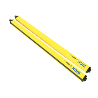
The following figure and table describe the C4000 Select sender unit DIP switch settings:
Beam code 1 Beam code 2 Description
OFF OFF No beam coding (uncoded)
ON OFF Beam code 1 enabled
OFF ON Beam code 2 enabled
ON ON No beam coding (uncoded)
Additional information regarding the scanning range can be found in section 4.2 “Beam
coding” on page 23.
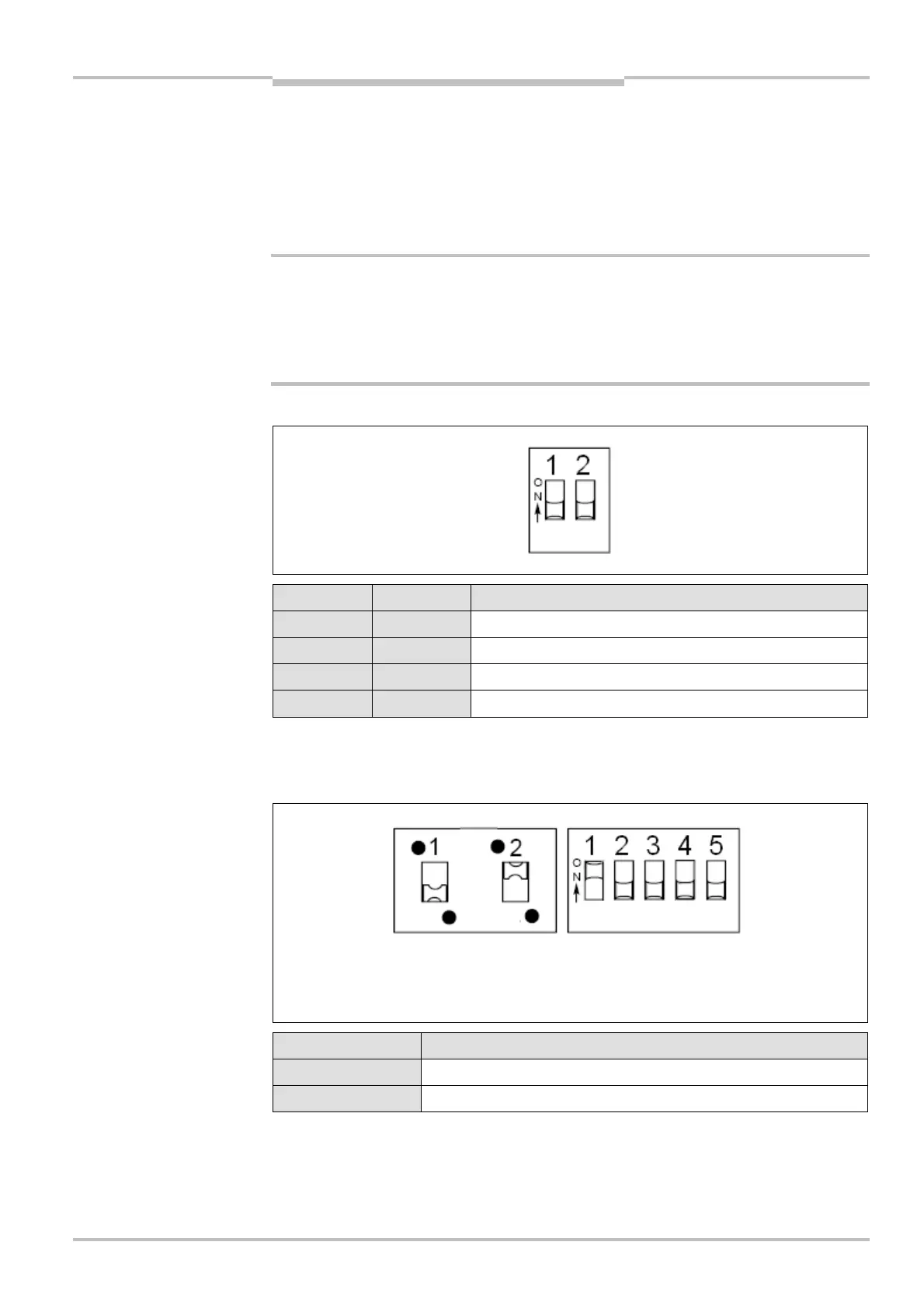
The following figure and table describe the C4000 Select receiver unit DIP switch settings:
High range select Description
OFF Scanning range set to low range (0…7.5 m)
ON Scanning range set to high range (5…21 m)
Additional information regarding the scanning range can be found in section 4.3 “Scanning
range” on page 25.
WARNING
unit DIP switch
unit DIP switch settings
ver unit DIP switches
ver unit DIP switch settings
for high range
2 = Beam code 2 select
2 = Extended I/O enable
2 = Beam code 2 select
3 = Floating blanking enable
4 = One beam floating blanking select
eam floating blanking select