Operating Instructions Chapter 4
C4000 Select
8012247/RI61/2007-11-30 © SICK AG • Industrial Safety Systems • Germany • All rights reserved 25
Configuration
Refer to chapter 4 “Configuration” on page 21 for additional details on DIP switch setting
requirements for beam coding.
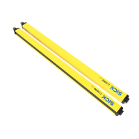
4.3 Scanning range
Scanning range defines the strength of the C4000 Select protective field beams in order to
allow for longer distances between the C4000 Select sender and receiver devices.
Match the scanning range with the protective field width!
The scanning range of the system (host, guest 1 and guest 2) must be adapted to the pro-
tective field width. If the scanning range is set to high range and the light curtains are
mounted below the minimum scanning range value, the safety light curtain may not reliab-
ly detect objects within the protective field. This would mean that the operator is at risk.
Two scanning ranges are selectable:
Physical resolution Selectable scanning ranges
0…7.5 m30 mm
5…21 m
7?segment display Description
No symbol Low range (0…7.5 m) selected
High range (5…21 m) selected
If the scanning range is set too low, the safety light curtain may not switch to green.
Tab. 11 shows the guaranteed scanning ranges for the system.
Deflector mirrors are available as accessories (see page 74f.). When used, deflector
mirrors will reduce the effective scanning range based on the number used (see
Tab. 13). When using deflector mirrors, you must configure the safety light curtain for
high scanning range.
Do not use deflector mirrors if the formation of droplets or heavy contamination of the
deflector mirrors is to be expected!
The formation of droplets of heavy contamination can be detrimental to the reflection
behavior. The protective function of the system will be affected and the system will thus
become unsafe. This would mean that the operator is at risk.
between C4000 Select sys-
tems based on same beam
coding configuration
WARNING
ranges
ment display on power-up for
scanning range
Notes
WARNING