Operating Instructions Chapter 7
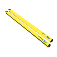
C4000 Select
8012247/RI61/2007-11-30 © SICK AG • Industrial Safety Systems • Germany • All rights reserved 47
Commissioning
7 Commissioning
Commissioning requires a thorough check by qualified safety personnel!
Before you operate a system protected by the C4000 Select safety light curtain for the first
t
ime, make sure that the system is first checked and released by qualified safety person-
nel. Please read the notes in chapter “On safety” on page 9.
7.1 Display sequence during power-up
After the system is activated, sender and receiver go through a power-up cycle. The 7@seg-
ment display indicates the device status during the power-up cycle.
The display values have the following meaning:
Display Meaning
, , , ,
, , ,
Testing the 7@segment display. All segments are activated
sequentially.
0.5 s (typical). Is displayed only at the receiver and only in operation
with high scanning range.
, or 0.5 s (typical). Non-coded operation or operation with code 1 or 2.
Other display Device error. See “Fault diagnosis” on page 52.
7.2 Aligning sender and receiver
After the light curtain has been mounted and connected, the sender and receiver must be
aligned in relation to each other. The light beams emitted by the sender must hit the re-
ceiver with pin-point accuracy. For additional information regarding the laser alignment
capability of the C4000 Select, see section 5.3 “Laser alignment” on page 41.
How to align sender and receiver in relation to each other:
Secure the plant/system. No dangerous movement possible!
Make sure that the dangerous state of the machine is (and remains) switched off! During
the alignment process, the outputs of the safety light curtain are not allowed to have any
effect on the machine.
Loosen the clamping bolts which hold the light curtain in place.
Switch on the power supply to the light curtain.
Watch the five (5) alignment LEDs on the receiver unit. As the number of illuminated
LEDs increases, an increased percentage of beams are aligned between sender and
receiver unit. When all beams are aligned, all five (5) LEDs will be illuminated. If all five
(5) LEDs are yellow, then there is a weak signal between sender and receiver. If all five
(5) LEDs are green, then the alignment is correct with adequate signal strength.
Using the clamping bolts, fix the light curtain in place.
Switch the power supply off and then back on again and check the five (5) alignment
LEDs to ensure alignment is still adequate.
WARNING
during the power-up cycle
WARNING