Chapter 11 Operating Instructions
C4000 Select
60 © SICK AG • Industrial Safety Systems • Germany • All rights reserved 8012247/RI61/2007-11-30
Technical specifications
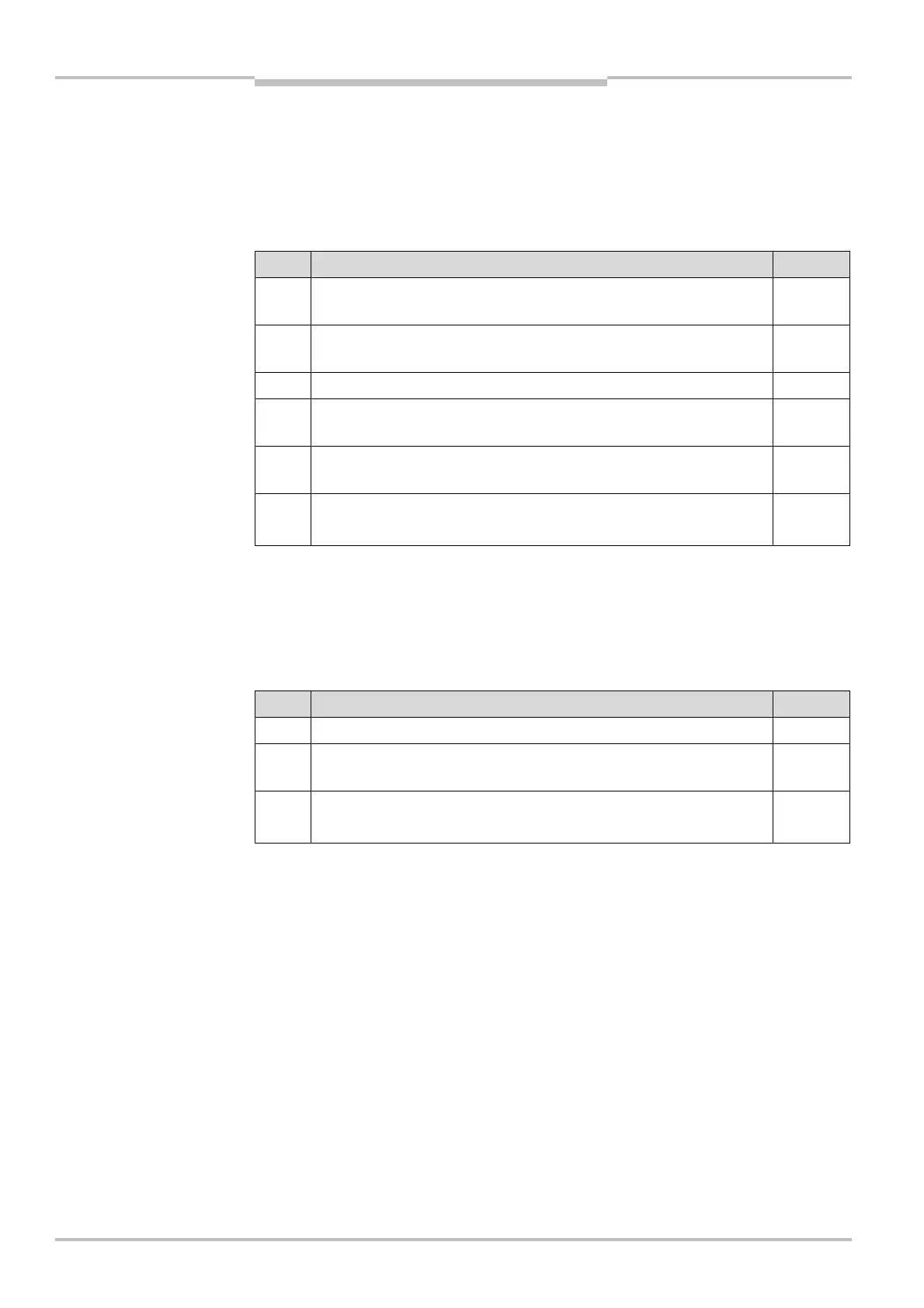
11.2.3 Calculating the guest 2 response time
The information presented in Tab. 31 “Response time of the C4000 Select for applications
with and without beam coding” also applies for C4000 Select sender/receiver pairs that
are in the guest 2 position. Identify the response time value that corresponds to your
guest 2 C4000 Select based on the beam code DIP switch setting (i.e. Uncoded, Beam
code 1 or Beam code 2 operation) and the protective height that is used.
Line Description Value
9 Enter the value for the guest 2 response time based on Tab. 31 for
the C4000 Select
10 If floating blanking is enabled, multiply the value on line 9 by 0.50
and enter the result as the line 10 value
11 Add lines 9 and 10 together. Enter the result in line 11 value
12 Multiply line 1 from the host response time calculation by 0.50 and
then add 2 ms. Enter the result as the line 12 value
13 Multiply line 4 from the guest 1 response time calculation by 0.50
and then add 2 ms. Enter the result as the line 13 value
14 Add lines 11, 12 and 13 together. Enter the result in line 14 value.
Line 14 value is the response time of the guest 2 device.
11.2.4 Response time calculation examples
Standalone C4000 Select system
The calculation example shown below is based on the following:
C4000 Select, 300 mm protective height, no beam coding, no floating blanking
Line Description Value
1 C4000 Select response time from Tab. 31 9 ms
2 When floating blanking is enabled, multiply the value from line 1 by
0.50 and enter the result as the value located for line 2
0 ms
3 Add lines 1 and 2 together and enter the value for line 3.
Line 3 value is the response time for the C4000 Select host.
9 ms
culation of guest 2 devices in
a host-guest 1-guest 2
system with C4000 Select
calculation for standalone
C4000 Select system