Operating Instructions Chapter 11
C4000 Select
8012247/RI61/2007-11-30 © SICK AG • Industrial Safety Systems • Germany • All rights reserved 55
Technical specifications
11 Technical specifications
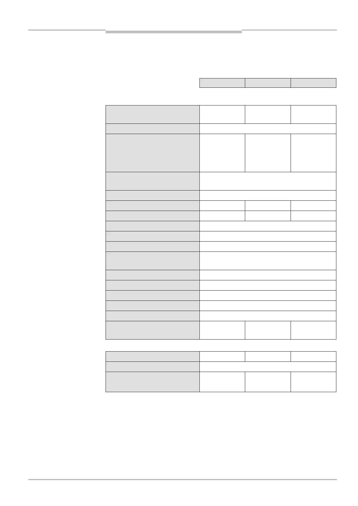
11.1 Data sheet
Minimum Typical Maximum
General system data
Protective field height, depending
on type
300 mm 1800 mm
Resolution
30 mm
Scanning range, DIP switch
configurable
Low range
0…6 m 0…7.5 m
8)
High range 5…19 m 5…21 m
8)
Protection class
(EN 50178:1997@10)
9)
III
Enclosure rating (IEC 60529)
IP 65
Supply voltage U
V
at device
10)
19.2 V DC 24 V DC 28.8 V DC
Residual ripple
11)
± 10%
Synchronization
Optical, without separate synchronization
Type according to IEC 61496 Type 4
SIL CL according to IEC 62061
12)
SIL CL 3
Category/performance level accor-
ding to EN ISO 13849@1:2006
12)
Category 4/PL e
SIL according to IEC 61508
SIL 3
PFH
d
stand-alone 1800 mm
1.5 × 10
-8
PFH
d
host-guest-guest 1800 mm 3.2 × 10
-8
Mission time/proof test interval
20 years
Category according to EN 954@1
13)
Category 4
Power-up delay of sender and
receiver before ready
8 s
Sender unit
Wavelength of sender 950 nm
Power consumption
See Tab. 30
Permissible line resistance
Supply lead 1
8)
On the utilization of this protective field width, it must be expected the yellow alignment LEDs will be yellow
(cleaning or realignment required). The system then only has a reserve of 30%.
9)
Safety extra-low voltage SELV/PELV.
10)
The external voltage supply must be capable of buffering brief mains voltage failures of 20 ms as specified in
EN 60204@1. Suitable power supplies are available as accessories from SICK.
11)
Within the limits of U
V
.
12)
For detailed information regarding the accurate interpretation of this data, please contact your local SICK
representative.
13)
EN 954@1 is valid until 29.11.2009. After this date, only its successor EN ISO 13849@1:2006 may be used.
Select