Chapter 5 Operating Instructions
C4000 Select
34 © SICK AG • Industrial Safety Systems • Germany • All rights reserved 8012247/RI61/2007-11-30
Installation and mounting
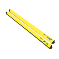
How to determine the minimum distance from reflective surfaces:
Determine the distance D [m] sender–receiver.
The minimum distance to the reflective surface a [mm] is shown in the diagram below
or may be calculated using the formula shown in Tab. 17.
Distance D [m]
sender–receiver
Calculation of the minimum distance a from reflective
surfaces
D 3 m a [mm] = 131
D > 3 m a [mm] = tan(2.5°) × 1000 × D [m] = 43.66 × D [m]
4
)
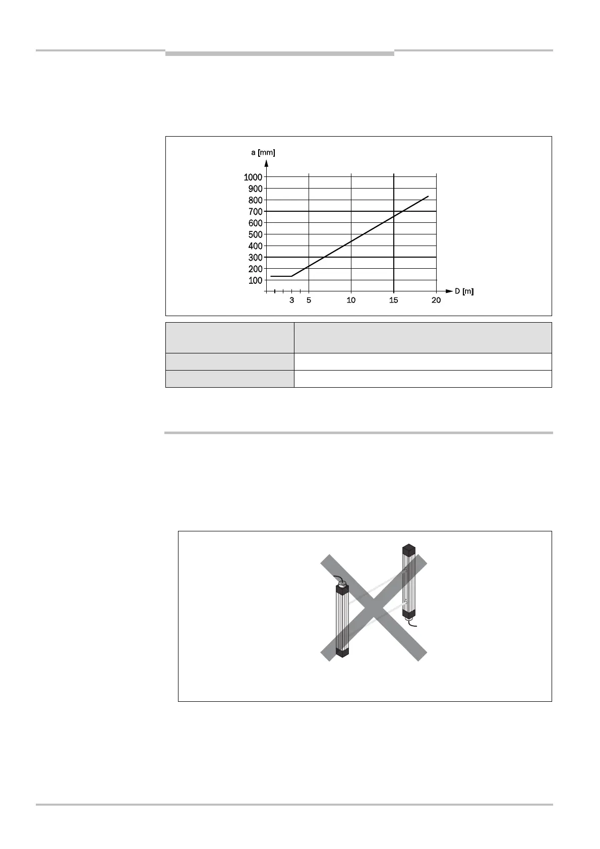
5.2 Steps for mounting the device
Special features to note during mounting:
Always mount the sender and receiver parallel to one another.
During mounting, ensure that sender and receiver are aligned correctly. The optical lens
systems of sender and receiver must be located in exact opposition to each other; the
status indicators must be mounted at the same height. The system connections of both
devices must point in the same direction.
4)
The maximum value used for D is 6 m for low scanning range and 19 m for high scanning range.
distance from reflective
surfaces
calculation of the minimum
distance to reflective
surfaces
WARNING
must not be rotated 180°
with respect to each other