Chapter 6 Operating Instructions
C4000 Select
44 © SICK AG • Industrial Safety Systems • Germany • All rights reserved 8012247/RI61/2007-11-30
Electrical installation
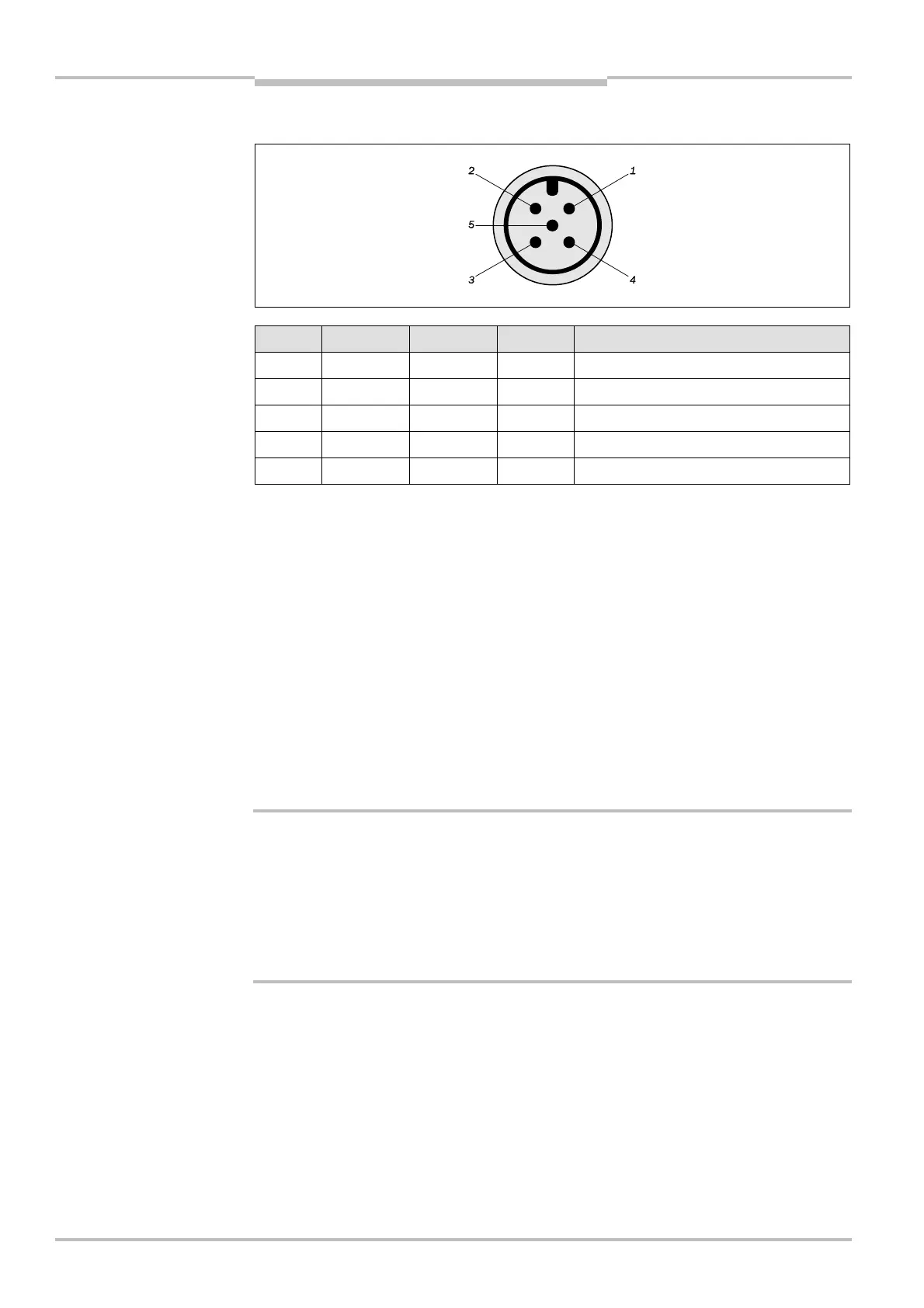
6.1 Bottom end cap with system connection M12× 5 male
Pin No. Wire Color
5)
Sender Receiver Description
1 Brown +24 V DC +24 V DC Supply voltage (+)
2 White – OSSD1 Output Signal Switching Device 1
3 Blue 0 V DC 0 V DC Supply voltage (–)
4 Black – OSSD2 Output Signal Switching Device 2
5 Gray FE FE Functional Earth
6.2 Bottom end cap with system connection M12× 5 male
and extended I/O connection M12× 5 female
In addition to the system connection, the C4000 Select may have an extended I/O connec-
tion included in the same end cap. This extended I/O connection is used for cascading ad-
ditional protective devices (e.g. another C4000 Select or SICK S300/S3000 safety laser
scanner). Connection of the safety-rated outputs associated with these additional casca-
ded devices occurs at the extended I/O connection of the C4000 Select receiver.
Only PNP-type semiconductor-based safety outputs may be connected via the extended
I/O connection. Electro-mechanical devices (i.e. contact-based devices) are strictly prohibi-
ted from being connected to the extended I/O connection.
When cascading C4000 Select devices via the extended I/O connection, the sender unit
may also utilize an extended I/O connection for ease of wiring.
Electro-mechical devices are not to be connected to the safety inputs on the extended
I/O connection!
Extended I/O connections allow you to cascade additional devices to the C4000 Select.
When implementing such a system, you are only allowed to connect PNP-type semiconduc-
tor safety-rated devices to the safety inputs on the extended I/O connection. Electro-
mechanical devices (e.g. emergency stops, safety interlock switches, etc.) shall not be
connected to the safety inputs on the extended I/O connection!
5)
Wire colors shown in this table are in accordance with SICK C4000 Select M12×5 cable accessories. When
utilizing other M12× 5 cable manufacturers’ cables, you may need to verify that the conductor colors shown in
this table correspond with the cable that you are using.
system connection M12
× 5
male
system connection M12
× 5
male
WARNING