Operating Instructions Chapter 6
C4000 Select
8012247/RI61/2007-11-30 © SICK AG • Industrial Safety Systems • Germany • All rights reserved 45
Electrical installation
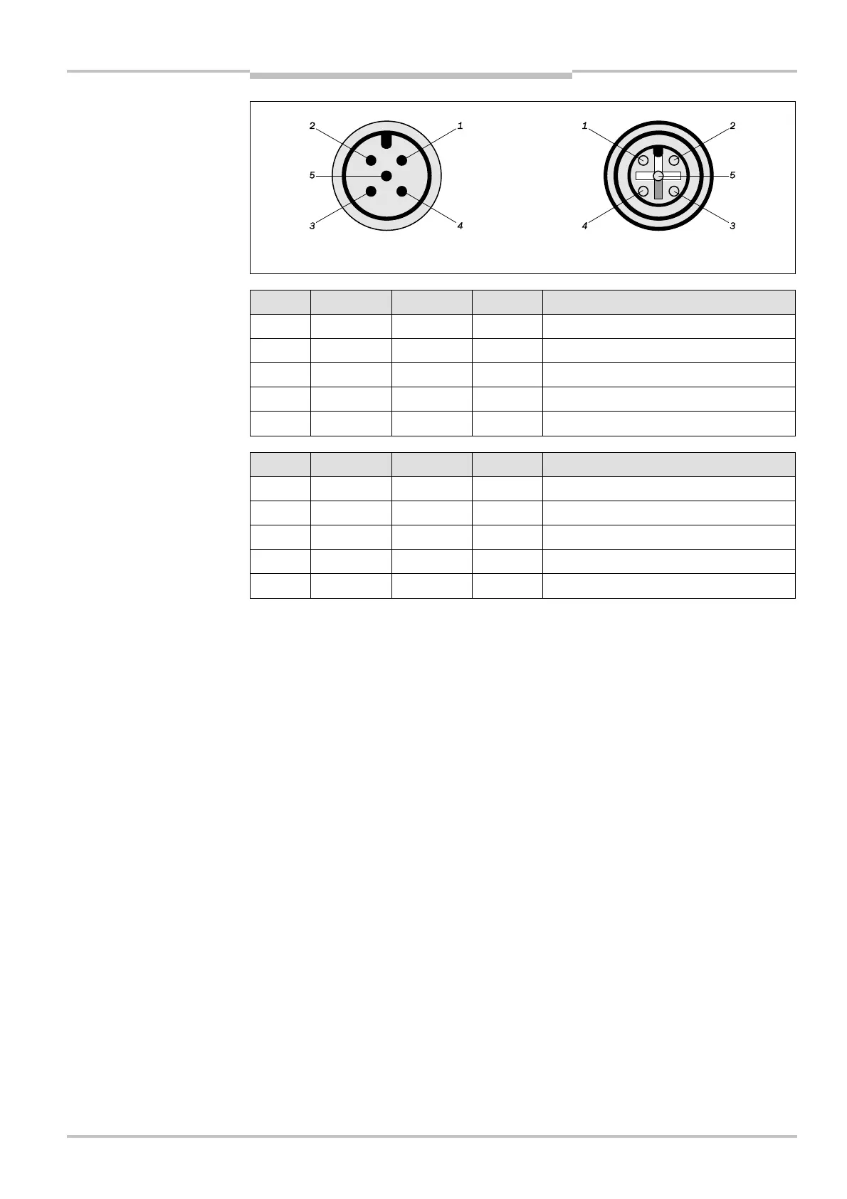
Male Female
Pin No. Wire Color
6)
Sender Receiver Description
1 Brown +24 V DC +24 V DC Supply voltage (+)
2 White – OSSD1 Output Signal Switching Device 1
3 Blue 0 V DC 0 V DC Supply voltage (–)
4 Black – OSSD2 Output Signal Switching Device 2
5 Gray FE FE Functional Earth
Pin No. Wire Color
6)
Sender Receiver Description
1 Brown +24 V DC +24 V DC Supply voltage (+)
2 White – IN1 Safe input 1
3 Blue 0 V DC 0 V DC Supply voltage (–)
4 Black – IN2 Safe input 2
5 Gray FE FE Functional Earth
6)
Wire colors shown in this table are in accordance with SICK C4000 Select M12×5 cable accessories. When
utilizing other M12× 5 cable manufacturers’ cables, you may need to verify that the conductor colors shown in
this table correspond with the cable that you are using.
system connection M12
× 5
male and M12
× 5 female
system connection M12
× 5
male
extended I/O connection
M12
× 5 female