40 GMS800 · Operating Instructions · 8013025 V1.2 · © SICK MAIHAK GmbH
Adjustment
Subject to change without notice
6.1 Adjustment introduction
6.1.1 Adjustment purpose
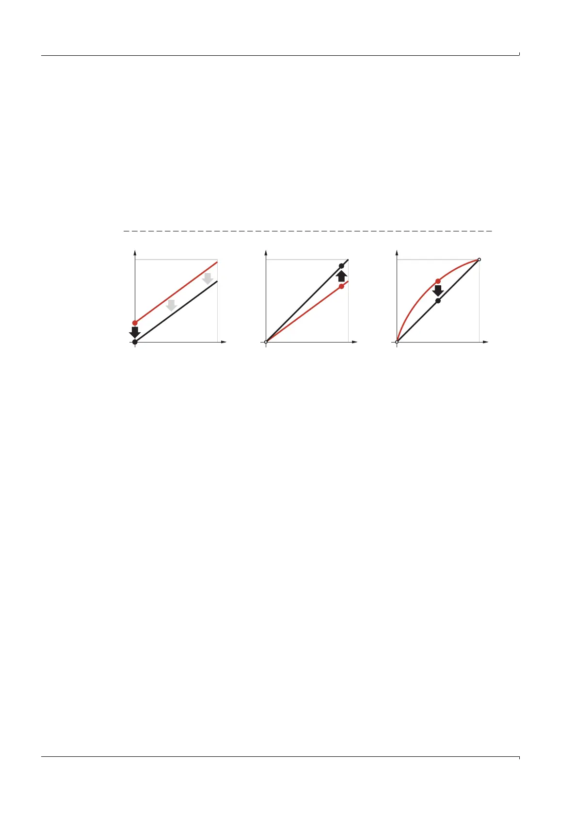
It is unavoidable that some of the properties of Analyzer modules will change during the
operating time. This changes measurement results even when external conditions remain
identical. This gradual change in measured results is known as drift. Zero point drift and
reference point drift exist. These drifts are measured during adjustment and the relation
between real concentration and measured value (characteristic curve) is corrected accord-
ingly (
→
Fig. 8).
The linearity of the characteristic curve (proportional relation between real value and
measured value) can also be checked and corrected afterwards (service function).
Fig. 8 Adjustment functions (schematic)
6.1.2
Principle adjustment procedure
1 A test gas is fed in.
2 A measured value (actual value) is determined with this test gas.
3 This actual value is then compared against the programmed nominal value.
4 The internal adjustment parameters are then corrected mathematically so that the
actual value then corresponds to the nominal value.
To attain complete adjustment, this procedure must be performed twice for each
measuring component – once for the zero point and once for the reference point.
Sequence control programs control these procedures (
→
Technical Information for Control
Unit).
0
M
C
0
M
C
0
M
C
Zero point adjustment Reference point adjustment Linearity adjustmentZero point adjustment

 Loading...


