GM35 Operating Instructions
Probe Model
Planning guidelines
20 © SICK MAIHAK GmbH • Germany · All rights reserved 8009389/07-2006
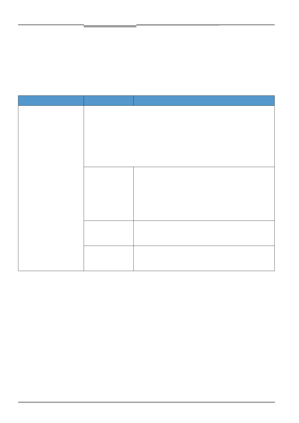
3.2 Project planning checklist
Step-by-step planning
The following checklist is intended to help you carry out and check the necessary planning
activities on a step-by-step basis before the system is commissioned. For technical specifi-
cations and dimension drawings of the system components, see page 99 and the following
Chapter.
Topic Task Measures/considerations
Determine the measuring
point
Observe any country-specific
legal stipulations (e.g. VDI
3950).
■ Ensure that the inlet and outlet sections are unimpeded.
✓ round duct cross-Chapter: 3x duct diameter
✓ rectangular cross-Chapter:
hydraulic diameter
✓ If these specifications cannot be met: inlet Chapter> outlet Chapter,
e.g.
2
/
3
:
1
/
3
; concentration distribution should be as homogeneous as possible.
■ Emissions
measuring point
✓ Obtain official approval for emissions measuring point.
✓ Calibration apertures should be provided at a point that is easily
accessible
✓ Take measures to avoid cross-interference between the GM35
and the calibration probe. The calibration gland should be
located at a minimum distance of 0.5 m (1.6 ft) upstream of the
measuring device.
■ Operating
conditions
✓ Observe the technical specifications for the duct and ambient
conditions.
✓ Gast temperature above/below dew point (dry/wet)
■ Pressure
at the measuring
point
✓ A mounting location with underpressure in the duct is ideal.
✓ For duct pressures > 10 hPa (0.15 psi), please contact SICK
MAIHAK to select the correct purge air fan type.
D
4F (cross-section)
U (circumference)
----------------------------------------------=
 Loading...


