GM35 Operating Instructions
Probe Model
Planning guidelines
24 © SICK MAIHAK GmbH • Germany · All rights reserved 8009389/07-2006
ATTENTION
The following safety precautions should be taken at the measuring point:
‡ Always shut down the installation before carrying out work on the duct
‡ Secure any components that are to be removed using wire, for example, to prevent
damage caused by falling parts
‡ Take suitable precautions to protect personnel from hot, explosive or toxic gases emitted
from the duct.
‡ When conducting welding work, always take the necessary safety precautions to prevent
explosions or fire in the duct atmosphere and on the duct insulation.
‡ If necessary, seal the mounting flange with a cover until the device is mounted (e.g. if
there is underpressure in the duct)
3.3.2 Exposing the duct
‡ If necessary, remove any insulation on the duct over an area of approx. 800 x 1500 mm
(W x H); an area of approx. 500 x 750 mm is sufficient for configurations without a purge-
air unit (see Fig. 7page 23).
‡ Store the removed insulation material safely for refitting, or use suitable, new insulation
material.
3.3.3 Flange with tube
Instructions for mounting the flange
• Standard flanges and special versions
The standard flange with tube supplied by SICK-MAIHAK has a total length of 240 mm
and an inside diameter of 125 mm. A version with a total length of 500 mm is available
for mounting locations with thick insulation, or brick ducts.
Special versions are available on request. Flanges manufactured by the customer, includ-
ing ANSI flanges, can also be used.
• Reinforcement with connection plates recommended
Due to the weight of the GM35 Transmitter/Receiver unit, we recommend that you rein-
force the flange tube with connection plates (provided by the customer).
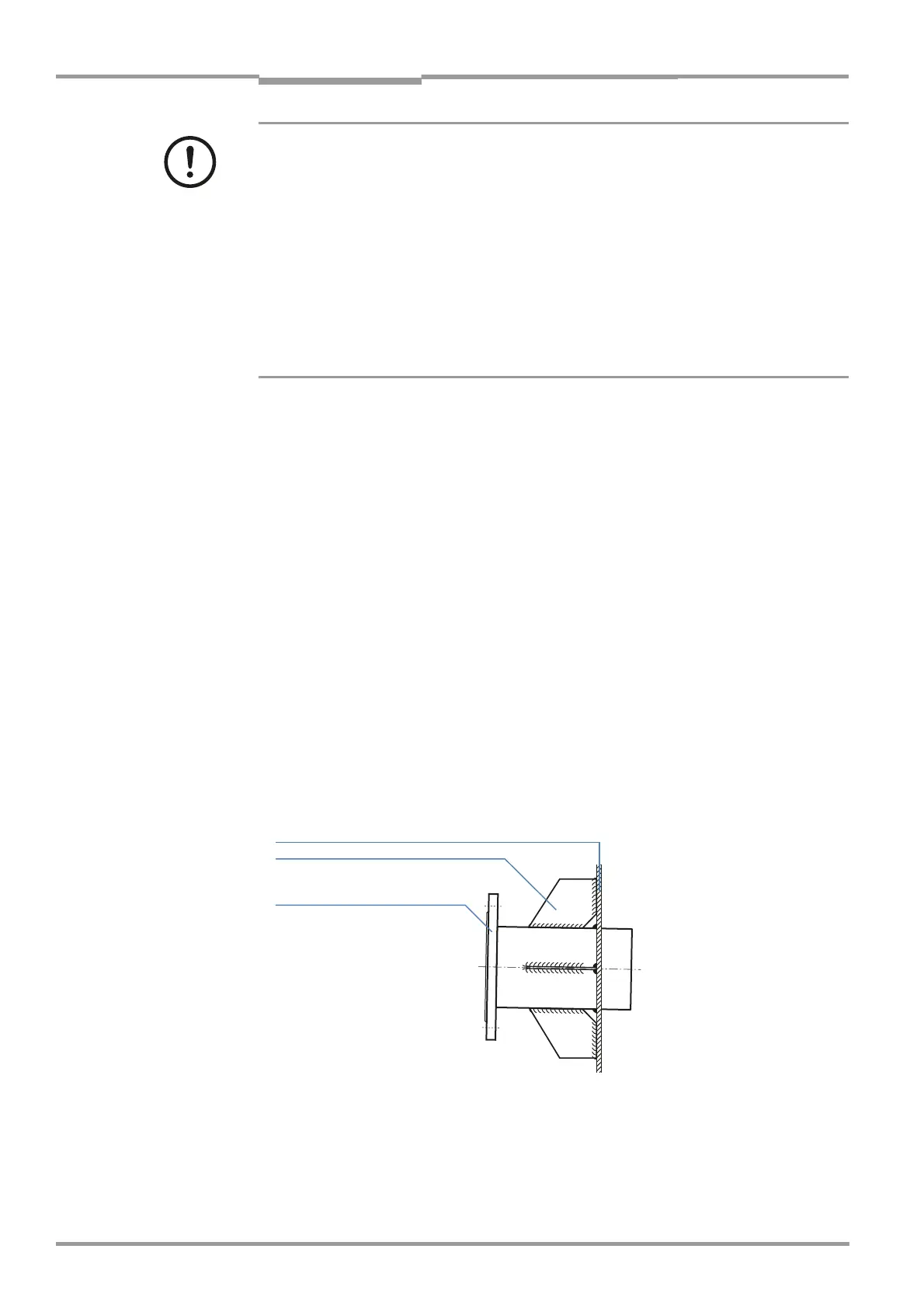
Fig. 8 Reinforcement using connection plates
Duct wall (steel)
Reinforcement plates (customer)
Flange with tube
 Loading...


