Operating Instructions GM35
Probe Model
Planning guidelines
8009389/07-2006 © SICK MAIHAK GmbH • Germany · All rights reserved 23
3.3 Preparations for installation
The procedures described below can be carried out by in-house technicians. They require
that all of the necessary decisions in the have been taken.
3.3.1 Preparations for installation at the measuring point
This Chapter describes the welding work required on the duct, including the preparation of
the fixing elements provided by the customer.
Completed? If you have already completed the activities described here prior to delivery of the device
using the "Product Information and Planning Guide", please check that you have done so
correctly in accordance with the information provided in this chapter.
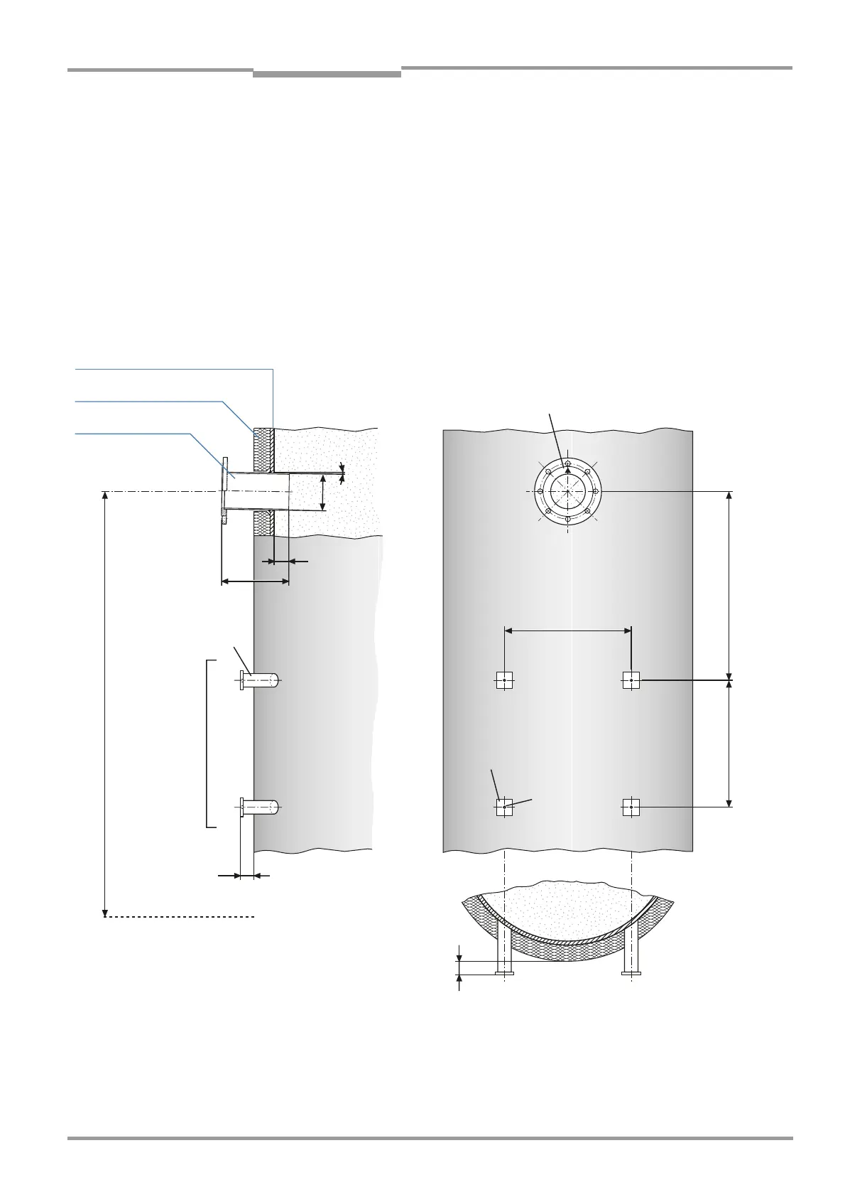
Fig. 7 Installation model: mounting flange and purge-air unit (duct diameter not representative)
30
L
50
470
M10
Ø133
1°
FL. 60x8x60
DIN 174
min. 700
Steel tube
50x5
DIN 2391
▲: Marking for installation position,
pointing in the direction of the gas flow
For securing the purge-air unit
1.3 – 1.5 m
50 mm (projection length in case of circular cross-section)
Working platform
470
Duct wall (steel)
Duct insulation
Flange with tube
Standard: L = 240 mm
All dimensions im mm, unless otherwise noted
 Loading...


