64 DUSTHUNTER T · Operating Instructions · 8012428 V 2.0 · © SICK MAIHAK GmbH Germany
Start-up and Parameter Settings
4.3 Installing the sender/receiver unit and reflector
4.3.1 Connecting the sender/receiver unit and reflector to the purge air supply
b
Check whether the purge air supply is available (the flow direction must be correct and
the purge air hoses fitted tight on the connections).
b
For purge air supply by the MCU-P control unit, push the DN 25 purge air hose onto the
connections of the sender/receiver unit and reflector and secure with D20-32 hose
clamps; with the optional external purge air unit, push the 40-25 adapters onto the
respective connections and secure with D20-32 hose clamps.
4.3.2 Fitting and connecting the sender/receiver unit and reflector on the duct
b
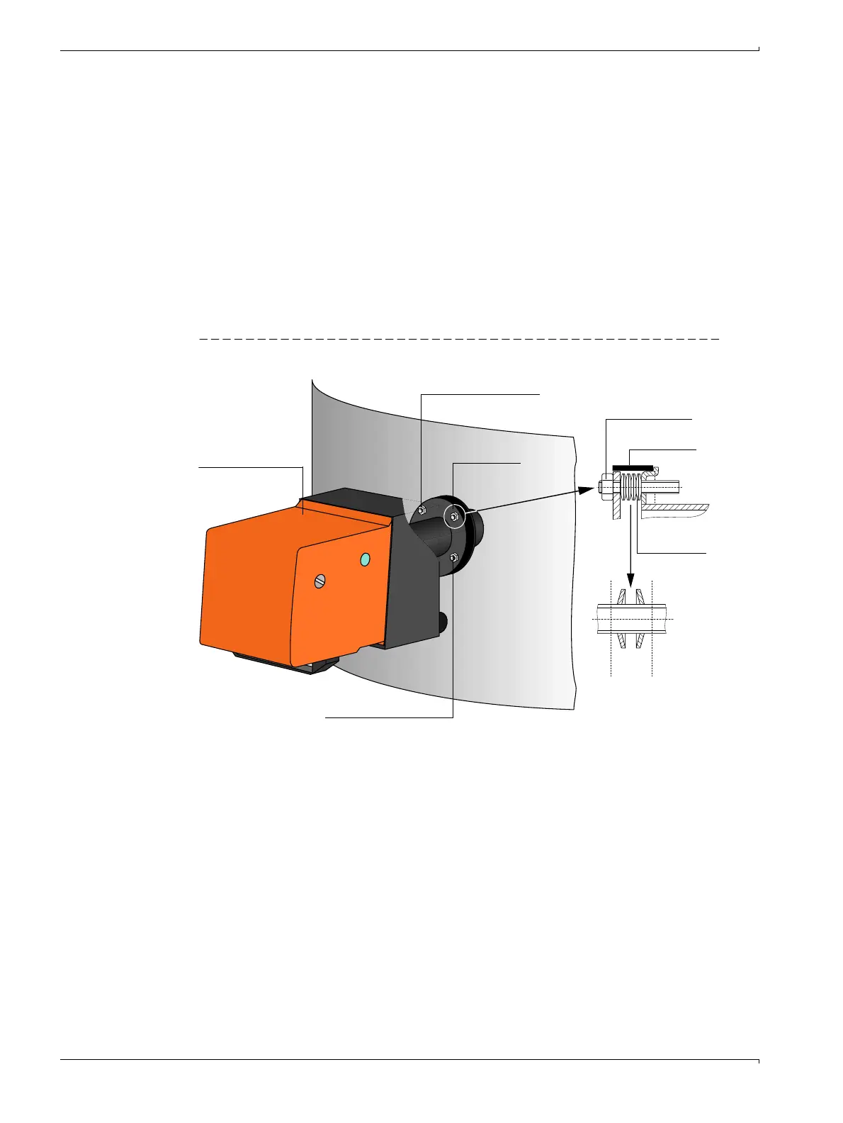
Attach the sender/receiver unit and reflector to the flange with tube according to Fig. 49 and
secure with the assembly kit.
Figure 49 Fitting the sender/receiver unit / reflector on the duct
b
Connect the connection cable to the MCU onto the plug-in connector on the sender/
receiver unit and screw tight.
b
On the DUSTHUNTER T200, connect the cable to connect the sender/receiver unit and
reflector to both components and screw tight.
b
Check the alignment of the optical axes of the sender/receiver unit and reflector (
→
p. 59, §4.2.2) and correct according to Fig. 49 when necessary.
Vertical alignment
Fixing point
Sender/
receiver unit
Horizontal alignment
Self-locking nut
Sealing tape
Cup springs
(4 pairs)
1 pair

 Loading...


