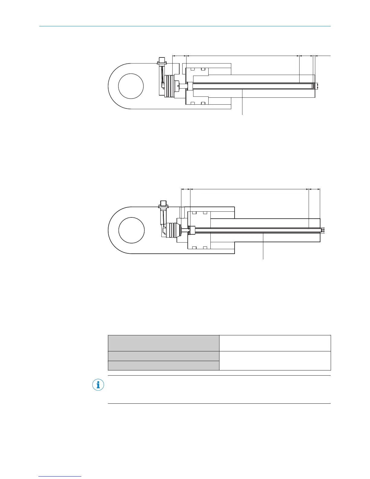
Figure 4: Encoder installed in the hydraulic cylinder – MAX48
1
Null zone
2
Measuring range
3
Damping
4
Diameter of the pressure pipe
5
Diameter of the piston rod bore hole
Figure 5: Encoder installed in the hydraulic cylinder – MAX30
1
Null zone
2
Measuring range
3
Damping
4
Diameter of the pressure pipe
5
Diameter of the piston rod bore hole
Table 5: Bore hole depth for the piston rod
1 = Null zone
MAX48: 30 mm
MAX30: 19.5 mm
2 = Measuring range
as per the applicable data sheet and selected
device variant
3 = Damping
NOTE
The total bore hole depth comprises the measuring range (2), the damping (3), and an
addition distance of 3 mm to the pressure pipe.
b
Prepare an installation cavity for the piston rod in accordance with the following
dimensions.
MOUNTING
4
8022793/ZXZ4/2018-07-24 | SICK O P E R A T I N G I N S T R U C T I O N S | MAX
13
Subject to change without notice