Table 6: Bore hole diameter for the piston rod
4
Ø Pressure pipe
5
Ø Bore hole in the piston rod
Ø 7 mm Ø 10 mm
Ø 10 mm Ø 12 mm / 13 mm
NOTICE
Ensure a consistent bore hole diameter of at least 12 mm.
Take into consideration the design and loading of the piston rod.
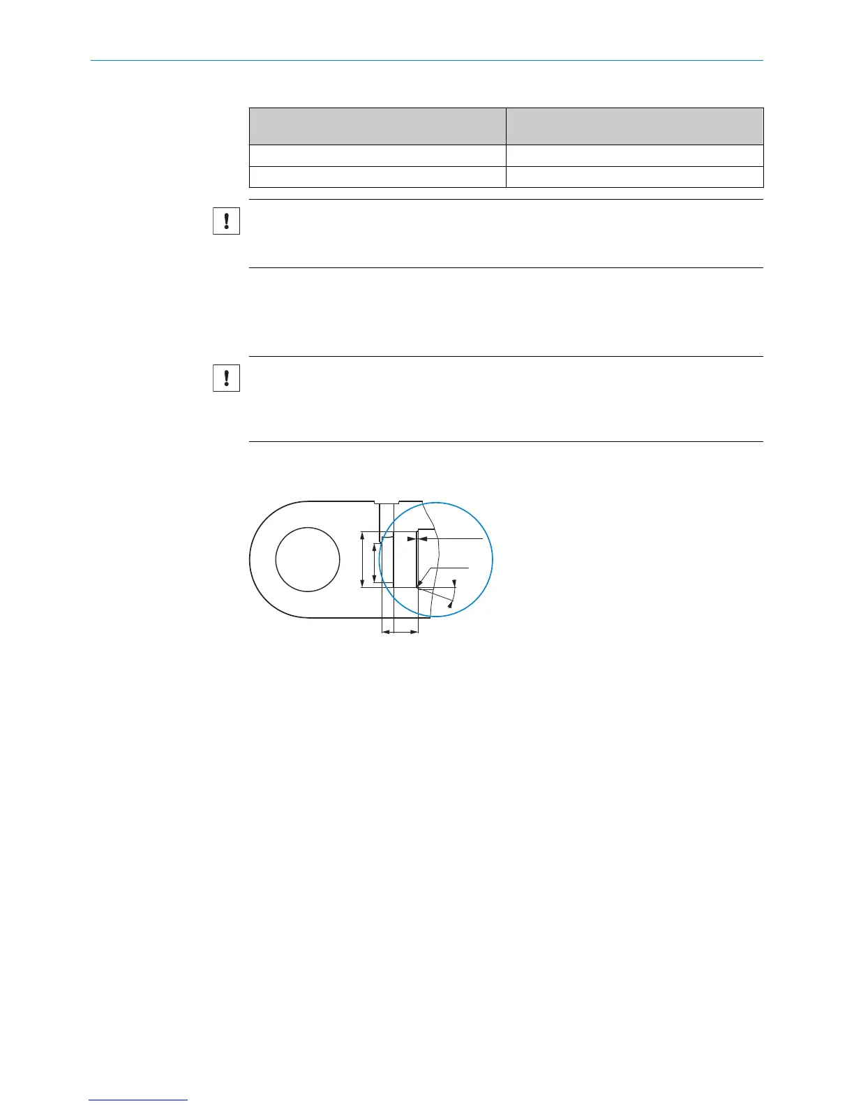
4.1.3 Insertion chamfer
To ensure proper and secure installation of the device in the cylinder, a insertion cham‐
fer must be provided.
NOTICE
Risk of damage to the device during installation
The device can be damaged by any sharp edges present at the transition from the cylin‐
der bore hole to the insertion chamfer on the O-ring.
b
Prepare an insertion chamfer with a radius of 0.6 mm at the end of the cylinder
bore hole.
Figure 6: Insertion chamfer
4.1.4 Bore hole for the retaining screw
b
Prepare a bore hole for the retaining screw in accordance with the following dimen‐
sions.
4 MOUNTING
14
O P E R A T I N G I N S T R U C T I O N S | MAX 8022793/ZXZ4/2018-07-24 | SICK
Subject to change without notice