Figure 8: Retaining screw on the encoder housing
Permissible tightening torque for fastening screw: 0.5 Nm ... 1.0 Nm (taking into
account the maximum force on the housing surface).
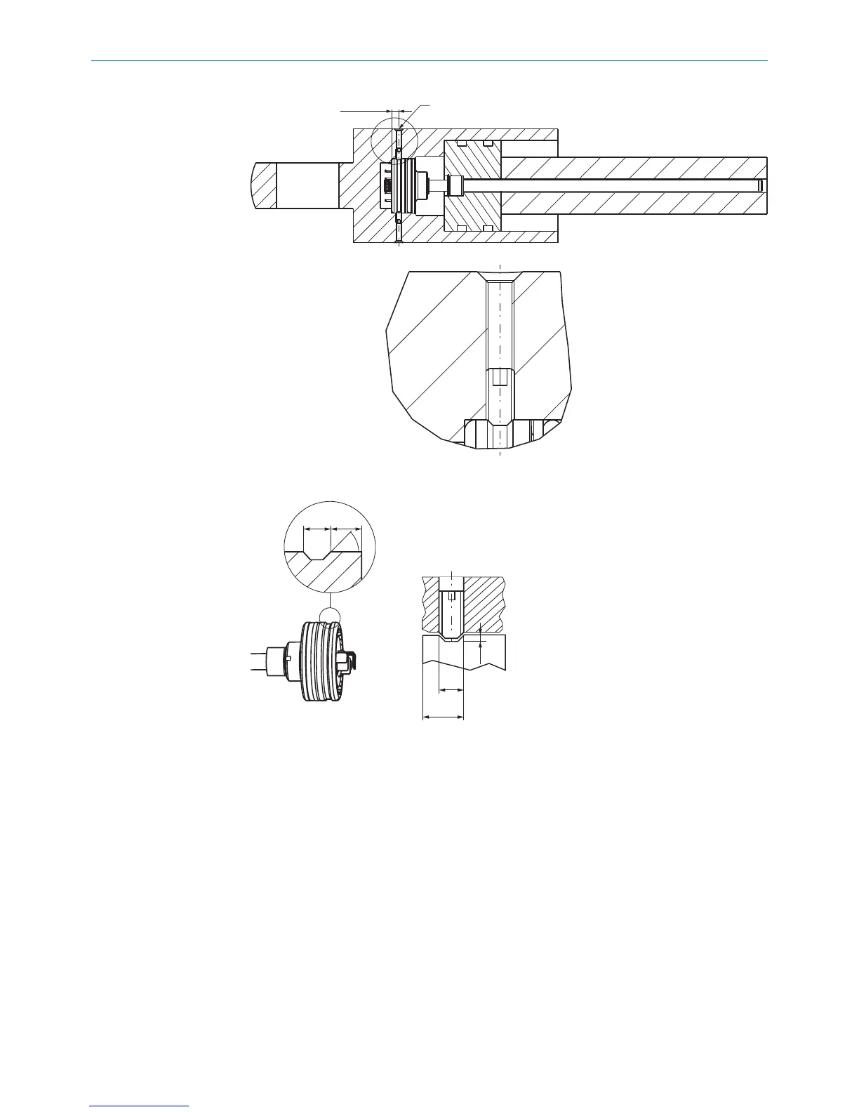
4.1.5 Bore hole for the electrical connection
M12 flange
b
Prepare an installation cavity for the connector system and flange plate in accor‐
dance with the following dimensions.
MOUNTING 4
8022793/ZXZ4/2018-07-24 | SICK O P E R A T I N G I N S T R U C T I O N S | MAX
15
Subject to change without notice