5 Electrical installation
5.1 Electrical connection
The encoder is equipped with an M12 connector system.
A variant with a cable connection is also available. Male device connectors must be
used in this case.
Enclosure ratings
To guarantee an IP69K enclosure rating (M12 connector system), a suitable mating
connector must be used.
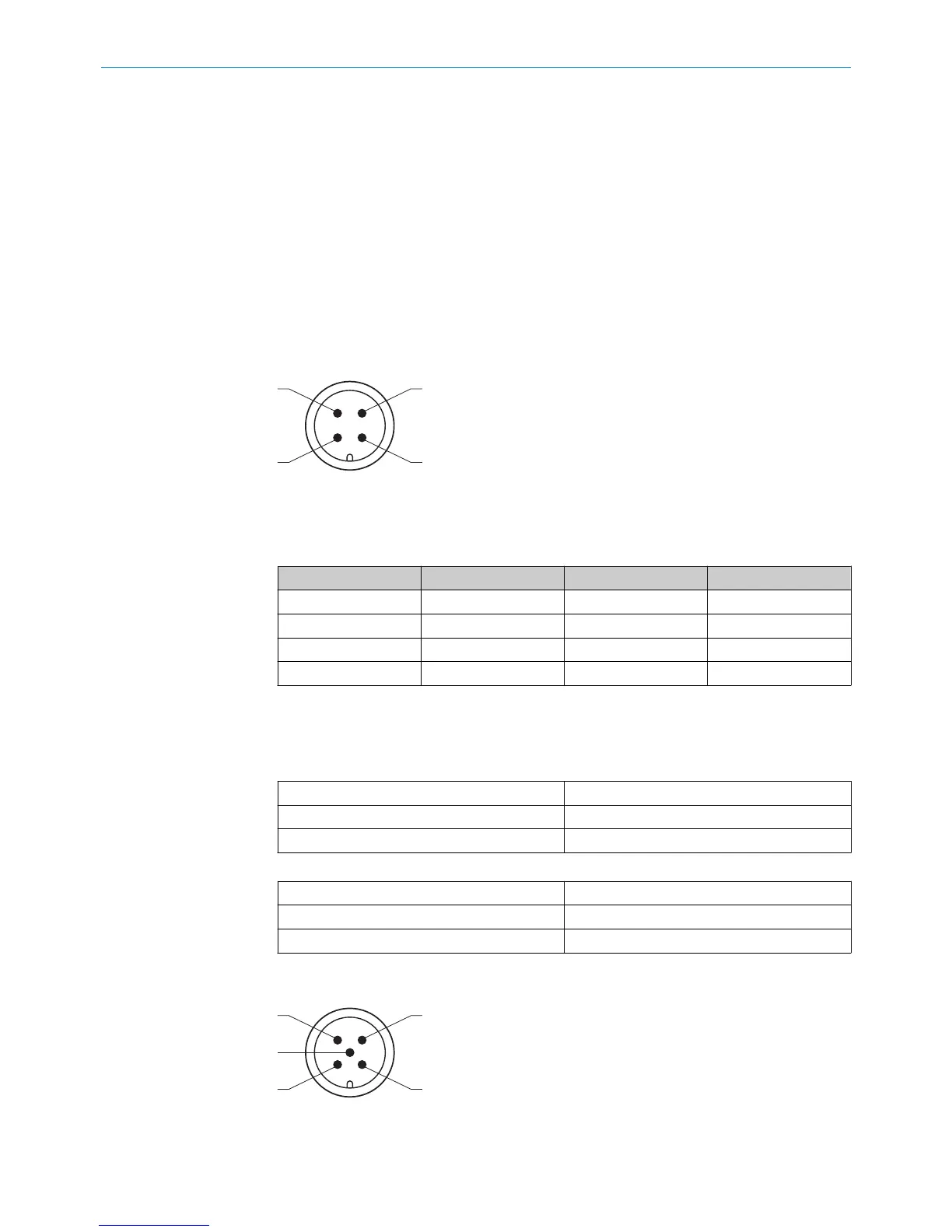
5.1.1 Connection diagram, pin assignment for 4-pin M12 male connector
Figure 24: Pin assignment for 4-pin M12 connector
Pin assignment as per position 13 of the type code.
Table 8: Pin assignment for 4-pin M12 connector
Type code A B M
12/24 VDC 1 1 2
GND (0 V) 3 3 3
Signal 4 2 4
n.c. 2 4 1
5.1.2 Cable connection diagram
Connection scheme as per position 13 (= “K”) of the type code.
Table 9: Allocation of wire colors (voltage)
12/24 VDC BR (brown)
GND (0 V) BL (blue)
Voltage signal BK (black)
Table 10: Allocation of wire colors (current)
12/24 VDC BR (brown)
GND (0 V) BL (blue)
Current signal WH (white)
5.1.3 Connection diagram, pin assignment for 5-pin M12 male connector
Figure 25: Pin assignment for 5-pin M12 connector
Pin assignment as per position 13 of the type code.
ELECTRICAL INSTALLATION 5
8022793/ZXZ4/2018-07-24 | SICK O P E R A T I N G I N S T R U C T I O N S | MAX
25
Subject to change without notice