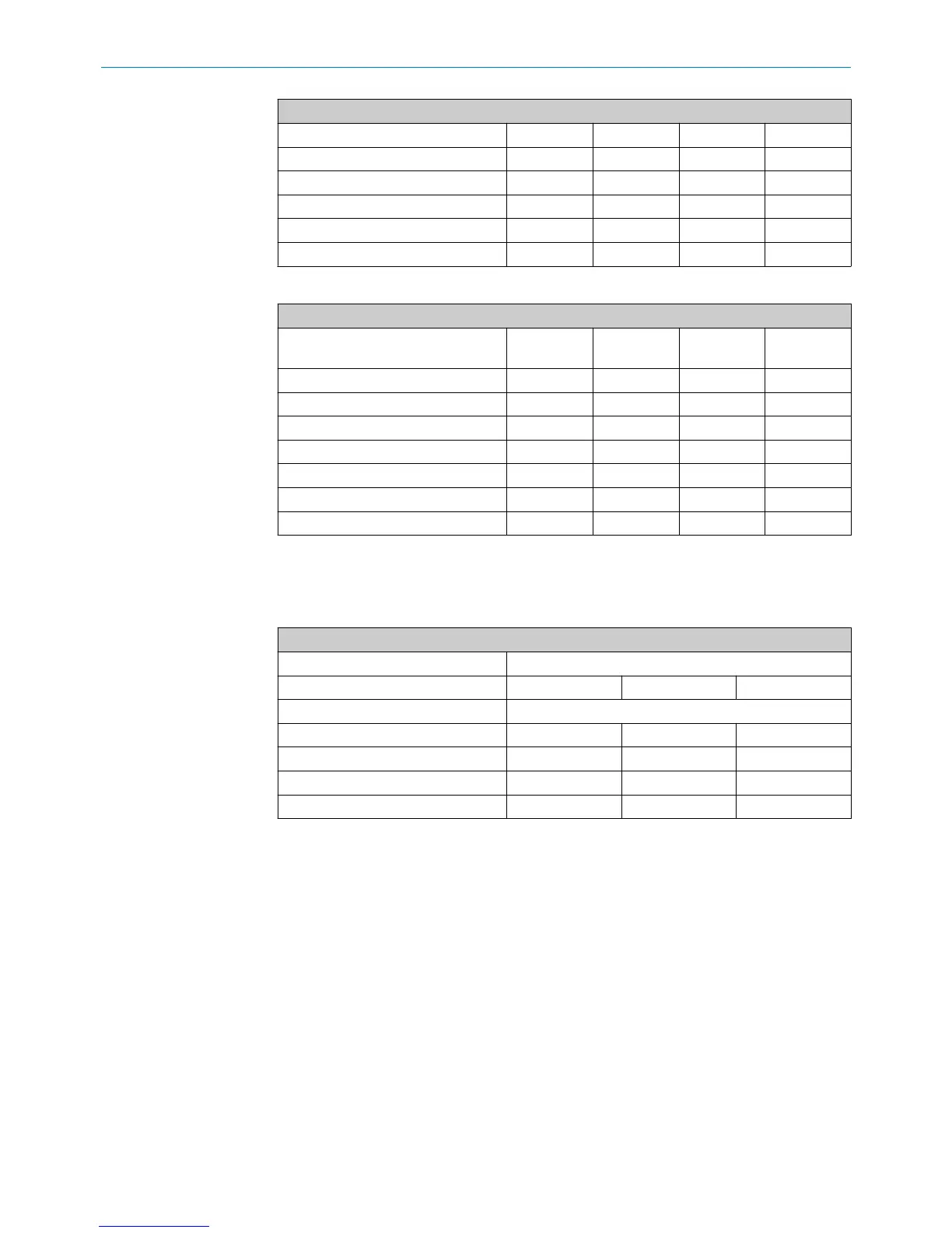
Example for a measuring range of 400 mm
Signal 0.5 ... 4.5 V 4 ... 20 mA 10 … 90% PDO
Range 4000 mV 16 mA 80% 4,000 digits
Zero/end point ± 1.0 mm ± 10 mV ± 0.04 mA ± 0.2% ± 10 digits
Position magnet ± 1.0 mm ± 10 mV ± 0.04 mA ± 0.2% ± 10 digits
Mechanical assembly ± 0.5 mm ± 5 mV ± 0.02 mA ± 0.1% ± 5 digits
Total of all tolerances ± 2.5 mm ± 25 mV ± 0.10 mA ± 0.5% ± 25 digits
Table 15: Zero end point
Example for a measuring range of 400 mm
Output Analog VDC Analog mA PWM (duty
cycle)
CANopen
SAE J1939
Signal 0.5 ... 4.50 V 4 ... 20 mA 10 … 90% PDO value
Zero point ± 25 mV ± 0.10 mA ± 0.5% ± 25 digits
min. zero point 0.475 V 3.90 mA 9.5% 275 digits
max. zero point 0.525 V 4.10 mA 10.5% 325 digits
End point (F.S.) ± 25 mV ± 0.10 mA ± 0.5% ± 25 digits
min. end point 4.475 V 19.90 mA 89.5% 3,975 digits
max. end point 4.525 V 20.10 mA 90.5% 4,025 digits
After installation of the encoder in the cylinder, deviations from the target values will
arise due to these permissible tolerances. These deviations must be taken into consid‐
eration when setting limit values in the controller:
Table 16: Deviation from the limit values
Typical values
Cylinder stroke (mm)
200 mm 400 mm 800 mm
Output signal Tolerances
Analog VDC ± 25 mV ± 25 mV ± 15 mV
Analog mA ± 0.20 mA ± 0.10 mA ± 0.05 mA
PWM (10 … 90% duty cycle) ± 1.0% ± 0.5% ± 0.25%
CANopen / SAE J1939 ± 25 digits ± 25 digits ± 25 digits
6.7 CAN bus protocols
CAN bus is a machine level, open field bus for serial data transmission between a cen‐
tral controller (master) and decentralized field devices (slaves). Various protocols can
be used for the data transmission depending on the application. The device can be
ordered with either CANopen or SAE J1939 protocol support. Each protocol is config‐
ured differently, which affects how the device is integrated into the network, and the
operating characteristics of the device.
CANopen
The CANopen version of the device is suitable for operation as a slave in CAN bus net‐
works using the CiA Standard DS 301 V3.0 data protocol. This protocol corresponds to
the DS 406 V3.1 encoder profile. The device is connected directly to the bus as a node
of the bus system. The device distinguishes between four different operating modes ini‐
tiated by the controller. These modes are defined in the CANopen standard:
COMMISSIONING 6
8022793/ZXZ4/2018-07-24 | SICK O P E R A T I N G I N S T R U C T I O N S | MAX
29
Subject to change without notice