Table 11: Pin assignment for 5-pin M12 connector
Type code C D
12/24 VDC 2 1
GND (0 V) 3 3
CAN_HI 4 4
CAN_LO 5 5
n.c. 1 2
5.1.4 Connection sequence
Connect the wires in the following sequence:
1. Connect the 12/24 VDC voltage supply.
2. Connect the GND (0 V).
3. Connect the signal.
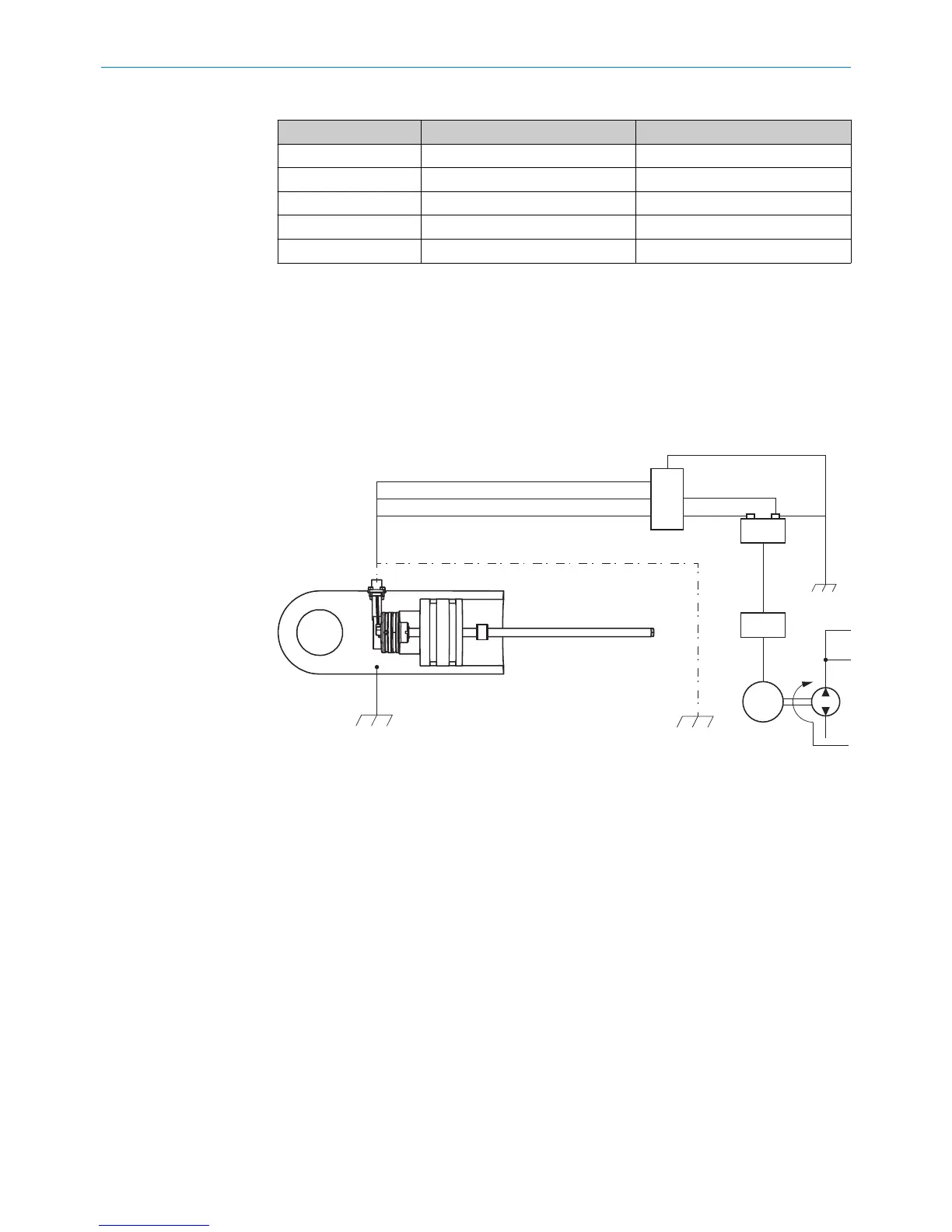
5.2 Connection diagram for vehicle electronics
Figure 26: Connection diagram
1
Chassis GND
2
Cable shielding (optional)
To guarantee fault-free operation of the device, the cylinder must be connected to
machine ground (Chassis GND).
The physical contact with another machine component equalizes the potential of the
cylinder. If the cylinder is mounted in an insulated manner, a separate grounding must
be provided, e.g., by connecting a ground strap directly to the cylinder.
Cable shielding
The encoder is adequately shielded by the cylinder when installed, and therefore has
not been provided with its own shielding. If a shielded cable is used, it is necessary to
check, depending on the application, whether one side or both sides of the shield
should be connected to machine ground. Any high voltage or high frequency fields in
the vicinity can influence the shielding and the signal in the cable.
5 ELECTRICAL INSTALLATION
26
O P E R A T I N G I N S T R U C T I O N S | MAX 8022793/ZXZ4/2018-07-24 | SICK
Subject to change without notice