4.1.6 Installation cavity for the position magnet
b
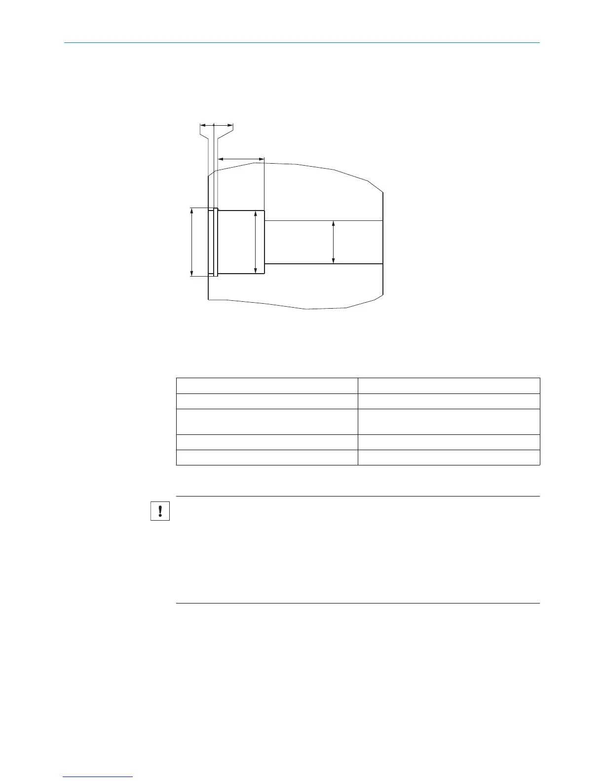
Prepare an installation cavity for the position magnet in accordance with the fol‐
lowing dimensions.
Figure 12: Dimensions of the position magnet installation cavity
4.2 Installing the position magnet
Table 7: Position magnet installation dimensions
1 Corrugated spring washer
see figure 37, page 51
2 Position magnet
17.4 x 12.0 x 10.6 mm
3 Circlip
DIN 472 - 18x1, alternatively see figure 39,
page 52
Diameter of the position magnet bore hole 17.5 + 0.1 mm
Depth of the position magnet bore hole 13.2 + 0.1 mm
Sequence of work steps:
NOTICE
b
Ensure that the retaining ring and the wave spring are made from non-magnetic
material (non-ferritic steel).
b
Ensure that the position magnet and the retaining ring do not rub against the pres‐
sure pipe.
°
Smalley retaining ring (see figure 39, page 52): does not contain any inter‐
nal edges or eyes for the pressure pipe.
b
Observe the operating pressures: see "Technical data", page 43.
MOUNTING 4
8022793/ZXZ4/2018-07-24 | SICK O P E R A T I N G I N S T R U C T I O N S | MAX
17
Subject to change without notice