6 Commissioning
6.1 Putting the encoder into operation
1. Check that the connectors have been connected correctly: see "Connection dia‐
gram, pin assignment for 4-pin M12 male connector", page 25.
2. Select a suitable fuse: see "Select a suitable fuse", page 27.
3. Set up the filter wiring: see "Set up the filter wiring - analog", page 27.
4. Put the device into operation.
5. Check the functioning of the encoder: see "Checking the functioning of the
encoder", page 38.
6.2 Select a suitable fuse
When selecting a suitable fuse, the transient peak current when switching on the
device for the time must be taken into consideration:
Table 12: Inrush current when switching the device on
Inrush current for an supply voltage of 12 VDC 2.5 A / 50 μsec typical
Inrush current for an supply voltage of 24 VDC 5.0 A / 50 μsec typical
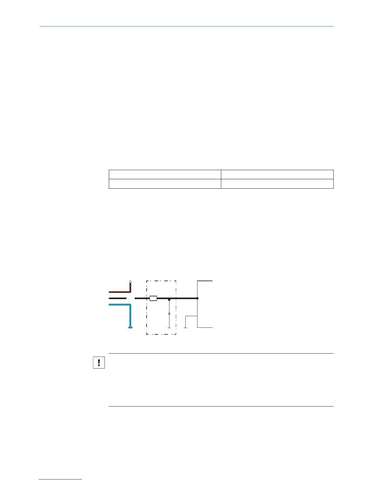
6.3 Set up the filter wiring - analog
Thermal noise, for example from resistors, becomes evident when the signal output is
amplified sufficiently. The supply voltage ripple (see "Technical data", page 43) and
other sources of interference, e.g., electromagnetic interference, can also affect the
quality of the analog output signal. To reduce the noise when acquiring analog mea‐
surement data, it is essential to use a filter.
A suitable filter, for example, is a combination of R1 = 50 Ω and C1 = 100 nF to 1 µF.
This will keep the signal delay time within the cycle time (internal measurement fre‐
quency) while not changing the dynamic behavior significantly.
Figure 27: Filter wiring
NOTICE
The A/D converter at the input of the installed electrical controller will determine the
resolution of the encoder, e.g.,:
•
8 bit = 256 steps
•
10 bit = 1,024 steps
•
12 bit = 4,096 steps
6.4 Power-up and output signal in the event of a fault
When switching on the device, the signal output is ≥ F.S.O = Full Scale Output. After that
the device is ready for use.
COMMISSIONING 6
8022793/ZXZ4/2018-07-24 | SICK O P E R A T I N G I N S T R U C T I O N S | MAX
27
Subject to change without notice