Table 13: Operational statuses and output signal
Output signal
F.S.O during power-up in the event of a fault
4.00 ... 20.00 mA
Unusable signal
> 21.0 mA
0.50 ... 4.50 V > 5.1 V
0.25 ... 4.50 V > 5.1 V
0.50 ... 9.50 V > 10.0 V
PWM (duty cycle) ≥ 99%
Digital: CANopen / SAE J1939 Boot message Error message “FFFF”
Fault:
a) Position magnet missing
b) Position magnet in null or cushion zone
c) Malfunction or failure of the magnetostrictive element
During power-up (see "Technical data", page 43), the output signal is defined as an
unusable signal. The machine controller must take this into consideration in its pro‐
cessing. After power-up, the linear encoder is ready for operation. The output signal
behaves as described in the event of a fault.
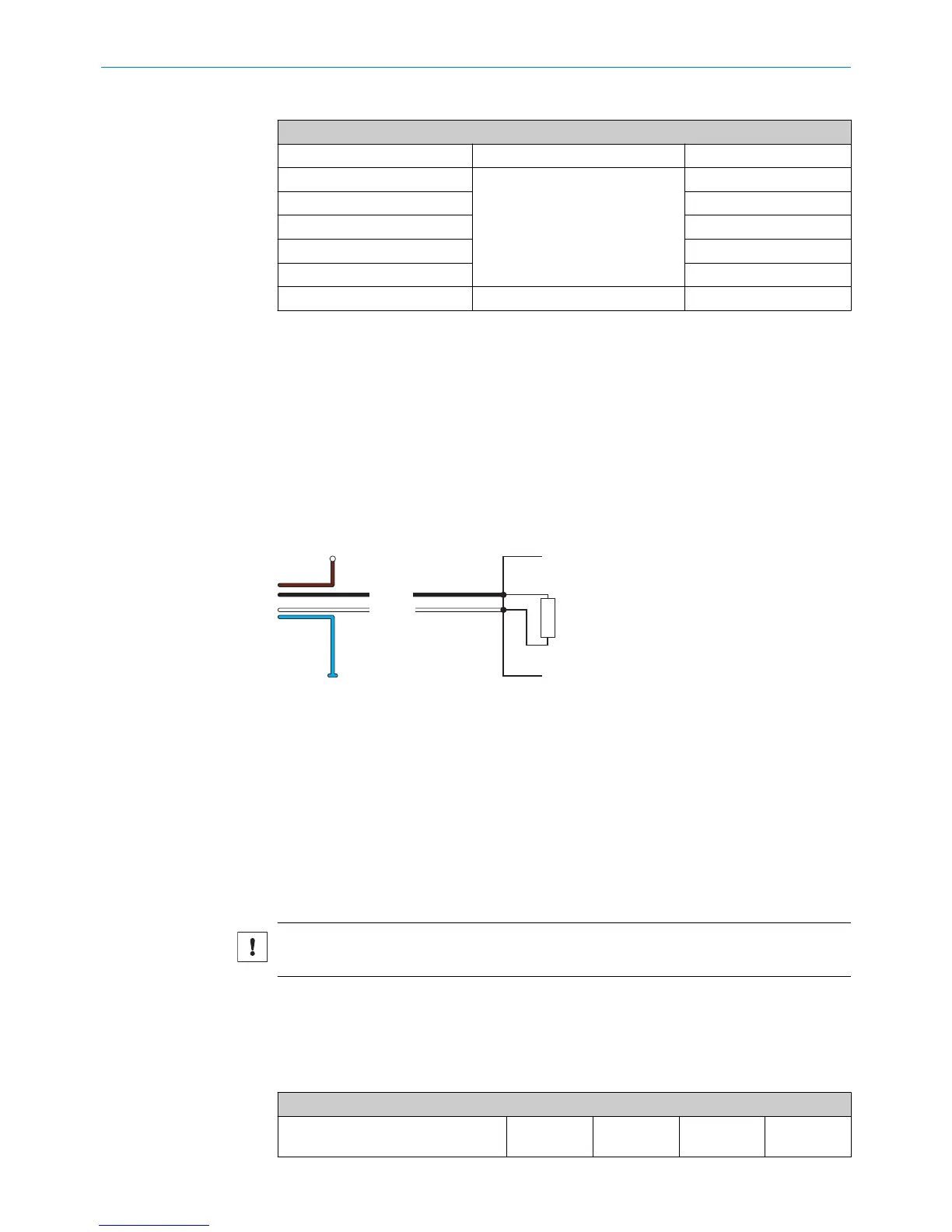
6.5 Bus termination - digital
Figure 28: Bus termination
Data transmission in the CAN bus is serial (2-wire bus system). The voltage difference
between the CAN_HI and CAN_LO data lines is one bit of information. To prevent signal
reflections, the data lines must be terminated with a 120 Ω terminator on the open bus
end. The terminator must be inserted between CAN_HI and CAN_LO.
6.6 Tolerance considerations for the set point
The set points (zero/end point) of the device are adjusted by the manufacturer to a tol‐
erance of ± 1 mm.
NOTICE
Further tolerances must be observed when installing the cylinder.
During teach-in, the piston rod moves to the zero point and to the end point in order to
eliminate all tolerances in the cylinder/encoder combination. The measured signals are
programmed in the controller accordingly. When operating the device without teach-in,
please note the following tolerance-related information:
Table 14: Tolerances when operating the device without teach-in
Example for a measuring range of 400 mm
Analog VDC Analog mA PWM (duty
cycle)
CANopen
SAE J1939
6 COMMISSIONING
28
O P E R A T I N G I N S T R U C T I O N S | MAX 8022793/ZXZ4/2018-07-24 | SICK
Subject to change without notice