4 Mounting
4.1 Preparation before installing the encoder
4.1.1 Installation cavity for the linear encoder
The method of installation depends on the cylinder design. Generally, the sensor is
installed from the piston rod side. It is also possible to install the sensor from the head
side of the cylinder.
The encoder dimensions are listed in the technical specifications: see "Encoder dimen‐
sions", page 48.
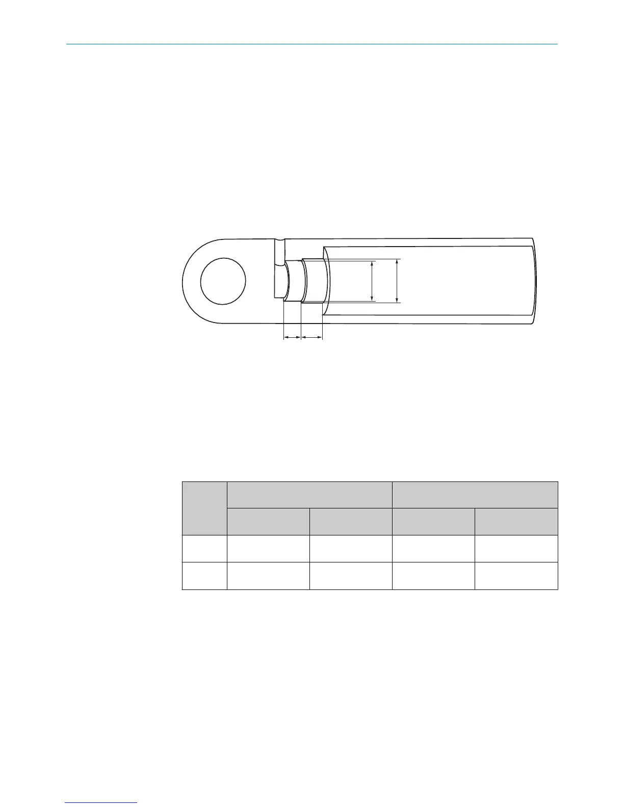
Fit dimensions and tolerances
Figure 3: Encoder installation cavity dimensions
1
Diameter for housing bore hole
2
Depth for housing bore hole
3
Installation cavity diameter for electrical connection
4
Installation cavity depth for electrical connection
b
Prepare an installation cavity for the encoder according to the following dimen‐
sions.
Table 4: Installation cavity for the housing and electrical connection
Type Installation cavity for housing Installation cavity for electrical connec‐
tion
1
Ø
2
Depth [D]
3
Ø min. ... Ø max.
4
Depth [d]
MAX48 48H8 21.2 mm + 0.2 d > 32.5 mm
d < 40 mm
≥ 10 mm
MAX30 31H8 22.7 mm +0.2 d > 26 mm
d < 28 mm
≥ 10 mm
Mean roughness value of the surface: Ra < 0.8 mm.
4
MOUNTING
12
O P E R A T I N G I N S T R U C T I O N S | MAX 8022793/ZXZ4/2018-07-24 | SICK
Subject to change without notice