Figure 20: Face side – MAX30
NOTICE
Risk of damage to the device during installation.
Forces acting on the load-bearing features of the housing can damage the device.
b
Do not apply any load on the pressure pipe or behind the head of the device
when mounting the sensor.
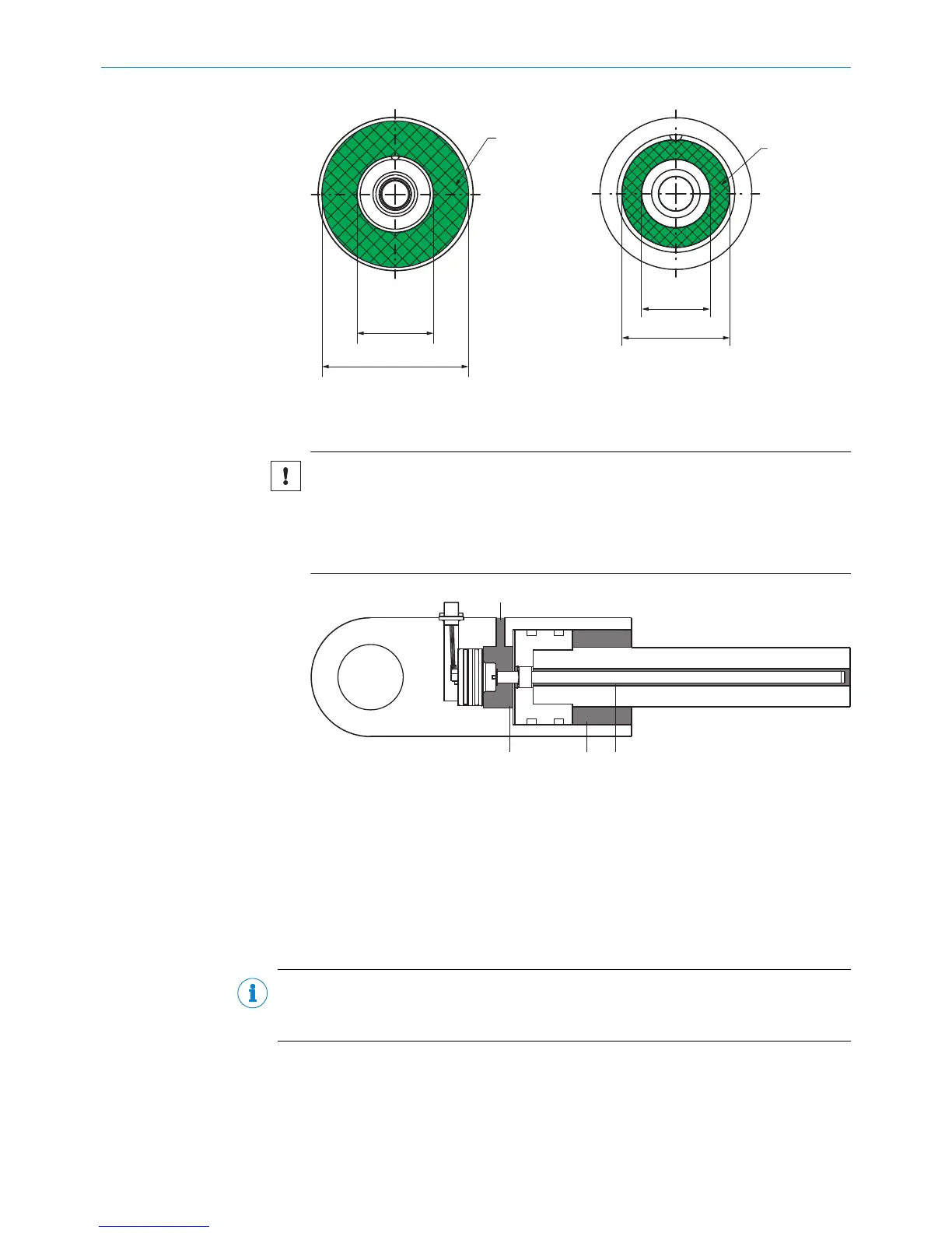
Figure 21: Areas requiring lubrication
1
Oil inlet
2
Areas requiring lubrication
7. Lubricate the indicated areas via the oil inlet.
4.3.3 Installation with an M12 connector system
The M12 connector system has an enclosure rating of IP69K and is pre-assembled
ready for installation.
NOTE
When selecting the mating connector, ensure that it also has an enclosure rating of
IP69K.
4 MOUNTING
20
O P E R A T I N G I N S T R U C T I O N S | MAX 8022793/ZXZ4/2018-07-24 | SICK
Subject to change without notice