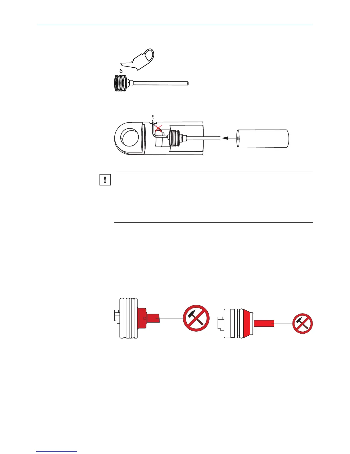
4.3.2 Insertion in the cylinder
Figure 15: Encoder lubrication points
1. Lubricate the O-ring, support ring and pressure pipe.
Figure 16: Tensile load at edges
NOTICE
Risk of damage to the connecting cables during installation.
Tensile loads and sharp edges can damage the stranded wires and connecting
cables of the connector system.
b
Avoid tensile loads and look out for sharp edges when installing the connec‐
tor system.
2. Carefully insert the encoder into the cylinder.
3. Guide the connecting cable carefully through the cylinder wall (bore hole).
4. Depending on the device variant, following the relevant steps below:
°
M12 male connector system: see "Installation with an M12 connector sys‐
tem", page 20.
°
Cable connector/cable gland: see "Installation with a cable connector and
cable gland", page 21.
5. Use a specially prepared sleeve (e.g., made from polyamide) to locate the device in
its final position.
6. Carefully tap in the sleeve using a mallet.
Figure 17: Profile side – MAX48 Figure 18: Profile side – MAX30
MOUNTING 4
8022793/ZXZ4/2018-07-24 | SICK O P E R A T I N G I N S T R U C T I O N S | MAX
19
Subject to change without notice