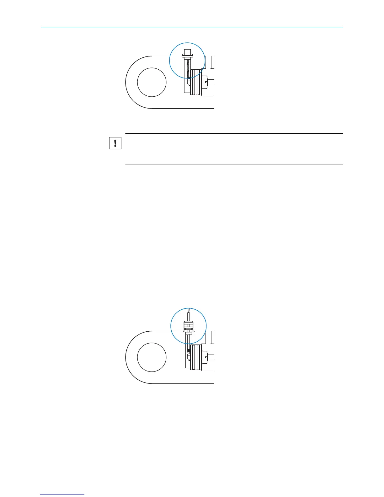
Figure 22: M12 connector system
1. Mount and engage the contact carrier in the flange plate.
NOTICE
b
When mounting the contact carrier in the flange, ensure the lug of the con‐
tact carrier is aligned correctly.
2. Press the flange plate into the bore in the cylinder wall.
3. Fasten the flange plate using suitable screws or rivets.
4. Proceed to the next step, see step 5, page 19.
Recommended screws for mounting the M12 flange
The screws should be selected so that no collision with the coupling nuts of the con‐
nected mating connectors can occur, e.g.,:
•
M3 socket head cap screw with flat head
•
DIN 912 hexagon socket head cap screw
•
ISO 14580 Torx screw
•
DIN 84 slotted-head screw
•
Comparable Phillips head screws or self-tapping screws
A soluble screw locking adhesive should be used when installing the screws.
Alternatively, the flange plate can be fastened using DIN 6660 button-head rivets.
4.3.4 Installation with a cable connector and cable gland
Figure 23: Encoder installed in the hydraulic cylinder with cable connector and cable gland
1. Guide the cable through the cable gland.
2. Mount the cable gland in the threaded bore.
3. Secure the tapered seal and coupling nut.
4. Proceed to the next step, see step 5, page 19.
MOUNTING 4
8022793/ZXZ4/2018-07-24 | SICK O P E R A T I N G I N S T R U C T I O N S | MAX
21
Subject to change without notice
 Loading...


