Position Meaning Description
13 Connection type A = M12 4-pin analog / PWM
(1 = VDC; 2 = n.c.; 3 = GND; 4 = SIG)
B = M12 4-pin analog / PWM
(1 = VDC; 2 = SIG; 3 = GND; 4 = n.c.)
M= M12 4-pin analog
(1 = n.c.; 2 = VDC; 3 = GND; 4 = SIG)
K = analog cable connection / PWM 3-wire cable
C = M12 5-pin digital
(1 = n.c.; 2 = VDC; 3 = GND; 4 = CAN_HI; 5 = CAN_LO)
D = M12 5-pin digital
(1 = VDC; 2 = n.c.; 3 = GND; 4 = CAN_HI; 5 = CAN_LO)
14 Connector length A = 60 mm M12
E = 100 mm M12
15 Measuring range
Position measurement
in 1 mm steps
e.g., 0300 = 50 ... 300 mm
16
17
18
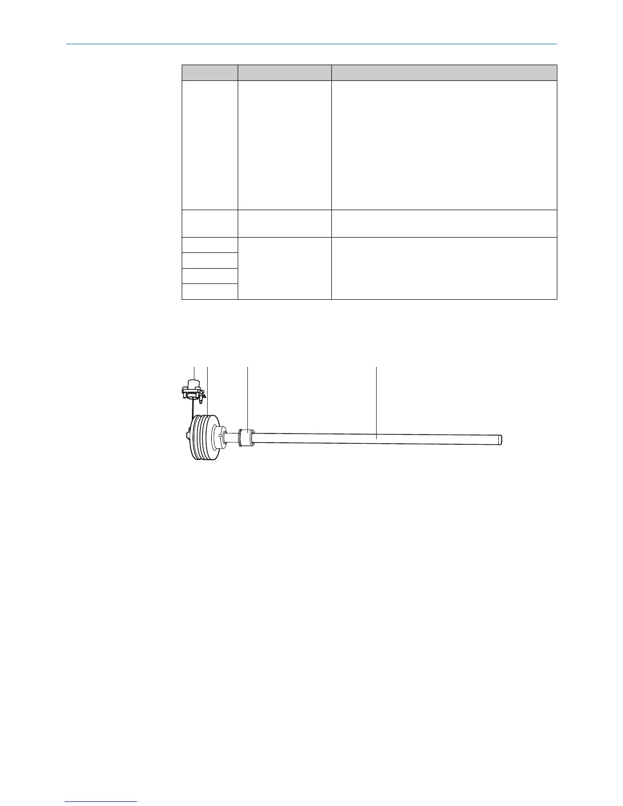
3.3 Construction and function
Construction of the device
Figure 1: MAX design
1
M12 connector system
2
Protective housing (electronics)
3
Position magnet
4
Pressure pipe
Connector system:
The M12 connector system requires very little time to attach. It is suitable for applica‐
tions in harsh environments up to IP69K (when using a suitable mating connector).
Protective housing (electronics):
The housing is designed to be installed in a hydraulic cylinder and protects the electron‐
ics against external influences.
Position magnet:
The position magnet is the only moving component in the measuring device when
installed in the piston. The position magnet is located inside the piston and moves over
the pressure pipe without contacting it. The magnet field that is produced during this
process defines the current position of the piston.
Pressure pipe:
The pressure pipe is a pressure-resistant structure that is immersed into the cylinder
piston rod. It contains the hermetically protected magnetostrictive sensing element.
3
PRODUCT DESCRIPTION
10
O P E R A T I N G I N S T R U C T I O N S | MAX 8022793/ZXZ4/2018-07-24 | SICK
Subject to change without notice