0
0 5 10 15 20 25 30
WAM window 2
50
100
150
200
250
Laser peak position 1
ScatterOffset
ScatterWidth
0
0 5 10 15 20 25 30
WAM window 2
50
100
150
200
250
Laser peak position 1
Scatter OffsetScatterWidth
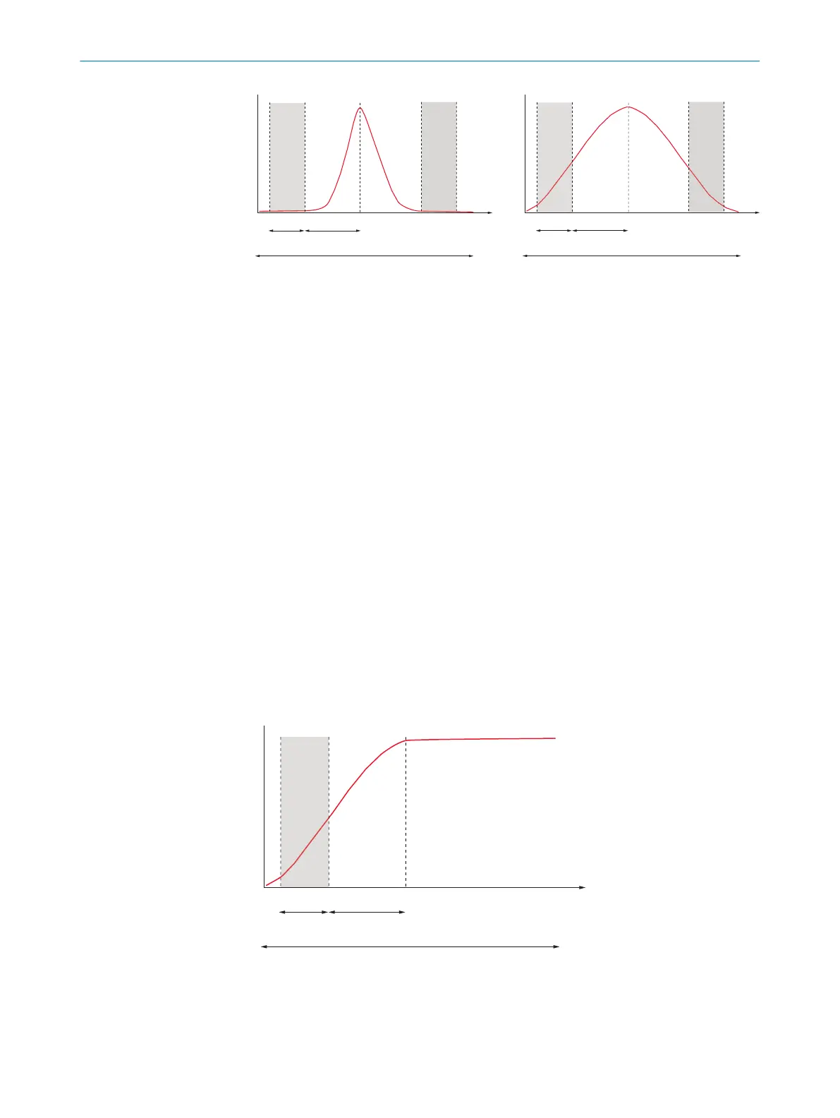
Figure 27: Examples of low scatter symmetric sampling (left) and high scatter symmetric sam‐
pling (right). The red line illustrates the laser signal in the extracted WAM window. The sampling
window is shown in gray.
1
Laser peak position
2
WAM window
You can set additional scatter parameters using GenICam™ or GenIStream, see "GenI‐
Stream API", page 16.
Advanced scatter parameters
The scatter sampling mode is defined by the Scatter Mode parameter. The following
options are available:
•
SymmetricSideBand: Sampling is done on both sides of the peak, as illustrated in
figure 27.
•
FrontSideBand: Sampling is done on rows in front of the peak in the readout, as
illustrated in figure 28.
•
BackSideBand: Sampling is done on the back side of the peak in the readout.
The WAM window is centered around the global maximum. If the image is saturated, the
WAM window is centered around the first saturated pixel. For general cases, such as
figure 27, it is recommended to use symmetric sampling to avoid saturated pixels in the
scatter data.
If the peak signal is saturated on one side, as in figure 28, FrontSideBand sampling can
be used to avoid the effects of saturation. Alternatively, BackSideBand sampling can be
used for an approximation of the signal saturation level.
0
0 5 10 15 20 25 30
WAM window 2
50
100
150
200
250
Laser peak position 1
ScatterOffset
ScatterWidth
Figure 28: Example of FrontSideBand scatter sampling. The sampling window is shown in gray.
1
Laser peak position
2
WAM window
8 CONFIGURATION
42
O P E R A T I N G I N S T R U C T I O N S | Ranger3 8020774/1D7Q/2022-03 | SICK
Subject to change without notice