20 / 109
BA 5846 en 05/2015
K..H K..M
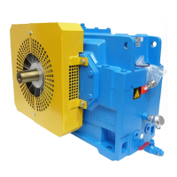
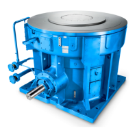
Fig. 4: Attachment points
For drive units where addon parts such as drive motor or addon coupling are fitted on the gear unit, an
additional attachment point may be required because of the shift in the centre of gravity.
Fig. 5: Attachment points on gear unit with motor
NOTICE
Material damage
Risk of damage to the eye bolts.
When attaching to eye bolts, no lateral pull against the direction in the eye plane must be allowed to
occur, as otherwise the eye bolts may break.
AB
45°45°
Fig. 6: Diagonal and lateral pull on eye bolts
A permitted diagonal pull in the direction
of the eye plane (maximum angle 45°)
B not permitted lateral pull against the
direction of the eye plane
For a detailed illustration of the gear unit and the position of the attachment points, refer to the drawings
in the orderspecific gearunit documentation.

 Loading...


