Installing peripherals
5
U24802-J-Z146-2-7600 RM400 C Models 41
Dokuschablonen Version 3.2 vom 25.10.93 © Siemens Nixdorf Informationssysteme AG 1993
Druck vom 12. 04.1999 16:17.03 Pfad: H:\Christoph\Manuale\PDF\RM\RM400C Betriebsanleitung\englisch\rm400.k05
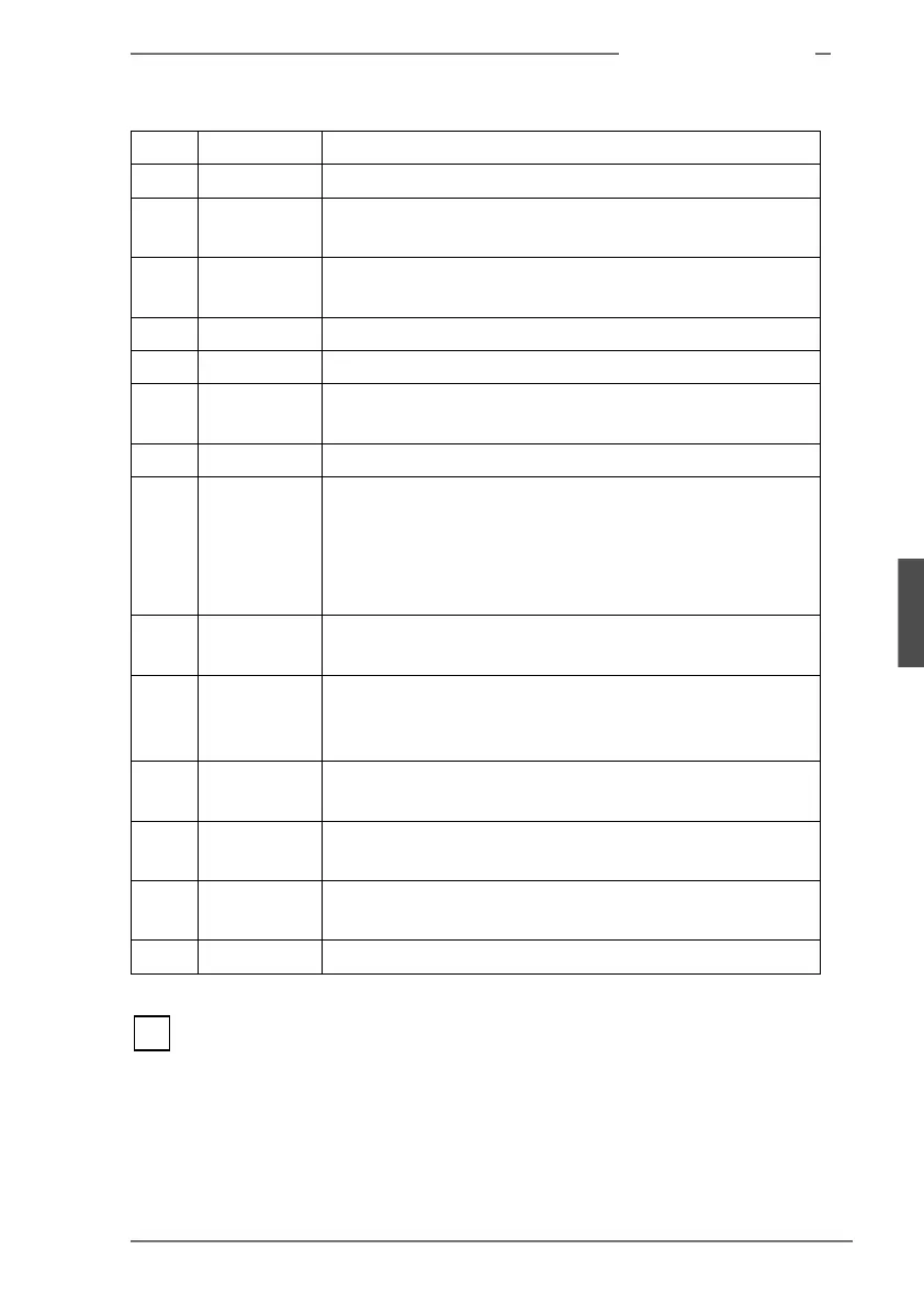
The two LAN ports (for twisted-pair (10BaseT) (22) and for Ethernet AUI
(24) cannot both be used at the same time.
* The RM400-C80 and -C90 models incorporate a double power connection (see
figure 8).
(1) MOUSE Mouse port
(2) KEYB. Keyboard port
(3) -
(8)
EISA 6 - 1 Slots for EISA controllers
(9) -
(13)
PCI 5 - 1 Slots for PCI controllers
(14) PRINTER System printer port (Bitronics interface)
(15) VGA Port for color monitors (SVGA)
(16) -
(19)
SCSI 1 - 4 Optional ports for SCSI devices (only in conjunction with
a controller in a slot)
(20) LEDs for CPU activity
(21) SCSI SCSI (external), port for single-ended SCSI devices that
can be attached to the internal SCSI bus. No terminator
is required because the system will where necessary
activate the internal terminating resistance automati-
cally.
(22) 10BT LAN port - twisted-pair (10BaseT), 8-pin connector for
Ethernet link
(23) LEDs indicating correct connection of the SCSI 0 port
(LED upper right) and activity on the Ethernet link
(send/receive, lower LEDs)
(24) Ethern. AUI LAN port - AUI (Attachment Unit Interface) port for
connecting cable to fan-out unit or transceiver
(25) CONSOLE/
COM1
First serial port (V.24, modem-capable)
(26)PORT1/
COM2
Second serial port (V.24, modem-capable)
(27) Power connector *
i
 Loading...