Installation
5.3 Mounting on the switching panel
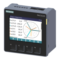
SENTRON PAC4200
60 Manual, 09/2008, A5E02316180B-01
5.3 Mounting on the switching panel
5.3.1 Tools
You require the following tools for installation:
● Cutting tool for the panel cutout
● Screwdriver PH2 cal. ISO 6789
Additional installation tools
● Cable clamp for strain relief of the RJ45 connector if the Ethernet interface of the device
is to be used.
5.3.2 Mounting dimensions
Mounting and clearance dimensions
You can find information on the cutout dimensions, frame dimensions and clearances in the
Chapter "Dimension drawings".
See also
Dimension drawings (Page 165)
5.3.3 Installation steps
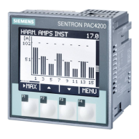
Proceed as follows to install the SENTRON PAC4200 in the switching panel:
Procedure
1. Cut a hole in the panel measuring 92.0
+0.8
x 92.0
+0.8
mm
2
(if not already available).
2. Discharge any static from your body. Observe the ESD guidelines in the Appendix.
CAUTION
Electrostatic sensitive devices
Discharge your body of any static electricity! Touch the grounded control cabinet, for
example, or a metal part that is connected to the building ground (heater, steel support).
3. Insert the device into the cutout from outside (Fig. "Installation cutout A").
4. Carry out all other installation steps from the inside of the switching panel.
 Loading...
