OPC UA communication
9.3 Using the S7-1500 as an OPC UA server
Communication
202 Function Manual, 11/2019, A5E03735815-AH
6. Click on the triangle in front of "Program blocks" in the area "OPC UA elements" to open
the "Program blocks" folder.
STEP 7 displays the following table for editing:
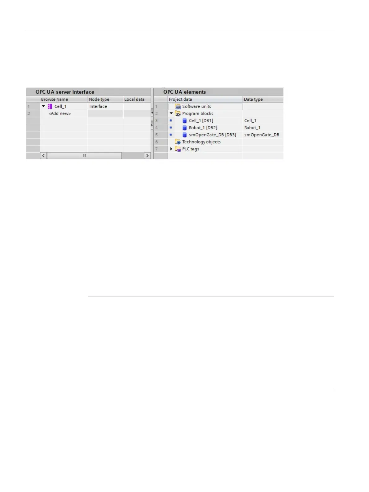
Figure 9-28 Editing the server interface
The editor is divided into two areas.
– OPC UA server interface
On the left is the root node of the server interface "Cell_1".
This interface is currently still empty: No OPC UA elements have been added to the
server interface yet.
– OPC UA elements
On the right are the OPC UA elements.
OPC UA elements are objects that have been created so far in the STEP 7 project
and have the property "Accessible from HMI/OPC UA".
You can add the OPC UA elements to the new server interface "Cell_1".
7. Drag the OPC UA elements into the "<Add new>" line of the new server interface.
Note
The following applies in general: If you store data
blocks or technology objects in the left
area of the table, STEP 7 (TIA Portal) creates an object in the server interface. The
elements of the data blocks are arranged as separate nodes below this.
If you store structures in the left area of the table, ST
E
P 7 creates a node for the structure
as a whole and nodes for each element of the structure.
The same applies to arrays: Again, STEP 7 creates a node for the array as a whole and
nodes for each element of the array.
When you place a method in the left a
rea of the table, STEP 7 creates a single node; the
arguments of the inserted method are displayed for information purposes.
In the example, you drag the "Gate_1_State" tag from the right area to the left area to
"<Add new>".
Then, drag the server method into the left area.
This server method is located within the "smOpenGate_DB [DB3]" data block in the right
area.

 Loading...


