Technical specifications
10.4 Connection box PN Plus interface assignment
Mobile Panel 277 RO
138 Operating Instructions, 10/2015, A5E36824256-AA
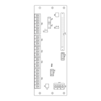
Terminal strip 1, for power supply, 3-pin
The figure below illustrates the assignment of terminal strip 1:
The safety and additional functions are connected to this terminal strip. The terminal strip
has a mechanical coding to prevent it from being mixed up with terminal strip 1. The figure
below illustrates the assignment of terminal strip 2:
STOP button
See also post connectors
1)
PLC auxiliary signals
1)
2)
Enabling button
See also post connectors and connection
examples
Active if Emergency Stop pressed
2)
Active if Mobile Panel connected
The "STOP button depressed" signal has no error detection and must therefore not be used
for safety-critical applications.
 Loading...