Technical specifications
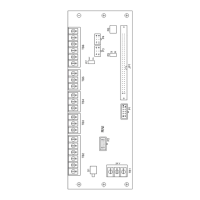
10.4 Connection box PN Plus interface assignment
Mobile Panel 277 RO
Operating Instructions, 10/2015, A5E36824256-AA
139
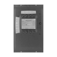
Typical circuit diagrams for connection box Plus
Typical circuit diagram: Mobile Panel 277 RO not connected and power supply switched on:
Typical circuit diagram: Mobile Panel 277 RO connected, power supply switched on and
Emergency Stop inactive:

 Loading...
