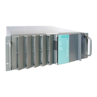
Hardware description
A.2 Internal interfaces
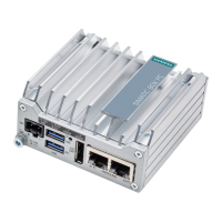
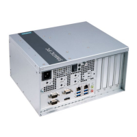
SIMATIC IPC847E
Operating Instructions, 10/2018, A5E43920357-AA
173
Internal interfaces
A.2.1
Pin assignment of the internal interfaces
Bus expansion Internal Bus expansion socket, used by PCIe bus and
special signals
Power supply Internal 4-pin 12 V ATX power connector (CPU-VRM
BIOS Recovery
1
Internal Replace jumper on pins 3-4 to run BIOS Recov-
1
Replace jumper on pins 1-2 to change locked ME
Monitoring of power supply fan, 8-pin, pin header
SATA Internal, e.g.,
7-pin SATA connector
Connection for PS serial ATA
Internal Voltage supply for serial ATA
Connection for device fan Internal Power supply, device fan monitoring (controlled),
Connection of SCSI activity
LED
Internal SCSI activity connector
Type JST B2B-PH-SM3-TB
Input for SCSI drive activity display
Internal USB3/USB2 interface Internal For connecting the USB cable to the front panel
Connection for USB interfaces on slot cover
Port 80 connector Internal Connection for Port 80 / mode switch
COM2 Internal Connection for COM2 on slot cover (see external
PEG interface (PCIe x16 sock-
Transfer interface between motherboard and bus
board
PCIe+special signal interface
A special USB stick is required (not included in scope of delivery; contact your local SIEMENS