Interface Submodules
13-11
S7-400, M7-400 Programmable Controllers Module Specifications
A5E00069467-07
13.4.1 Pin Assignments
Socket X1, X2 COMa, COMb
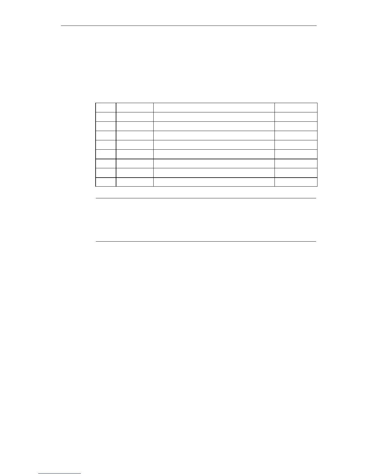
Table 13-8 Socket X1, X2 IF 962-COM (9-Pin Sub D Plug Connector)
1
DCD Receive signal level Input
2 RxD Receive data Input
3 TxD Transmitted data Output
4 DTR Data terminal ready Output
5 Signal GND Operational ground (GND
int
) –
6 DSR Data set ready Input
7 RTS Request to send Output
8 CTS Clear to send Input
9 RI Ring indicator (incoming call) Input
Note
Operational ground (signal GND) at the COMa or COMb ports is referenced to
internal ground.
Suitable measures may be required on the process side to avoid ground loops.