Interface Submodules
13-42
S7-400, M7-400 Programmable Controllers Module Specifications
A5E00069467-07
13.7.3 Connecting Loads/Actuators to Analog Outputs
Abbreviations Used
The abbreviations used in Figures 13-20 to 13-21 have the following meanings:
QI: Analog output current
QV: Analog output voltage
S: Reference potential of the analog circuit
R
L
: Load resistance
Figures 13-20 and 13-21 show you how you must connect loads/actuators to the
current or voltage outputs of the analog output module.
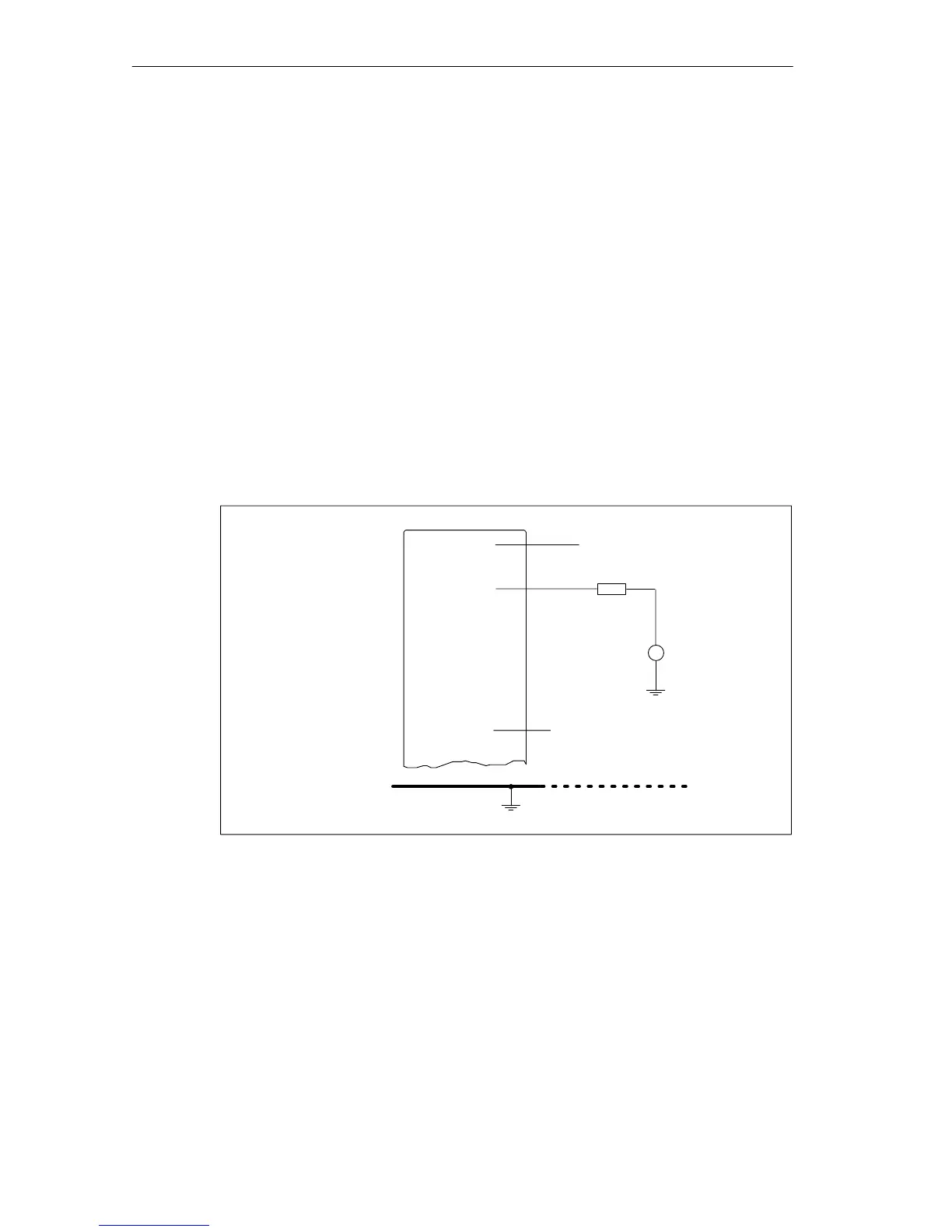
Connecting Loads to the Current Output
The following figure shows wiring on one channel as an example.
+24 V
R
L
L
+
QI
Ground bus
V
CM
M0 V
Figure 13-20 Connecting Loads/Actuators via a Two-Wire Connection to a Current Output
 Loading...


