EasyManuals Logo

Siemens Simatic M7-400 User Manual

Siemens Simatic M7-400
638 pages
To Next Page IconTo Next Page
To Previous Page IconTo Previous Page
Page #539 background imageLoading...
Page #539 background image
Interface Submodules
13-43
S7-400, M7-400 Programmable Controllers Module Specifications
A5E00069467-07
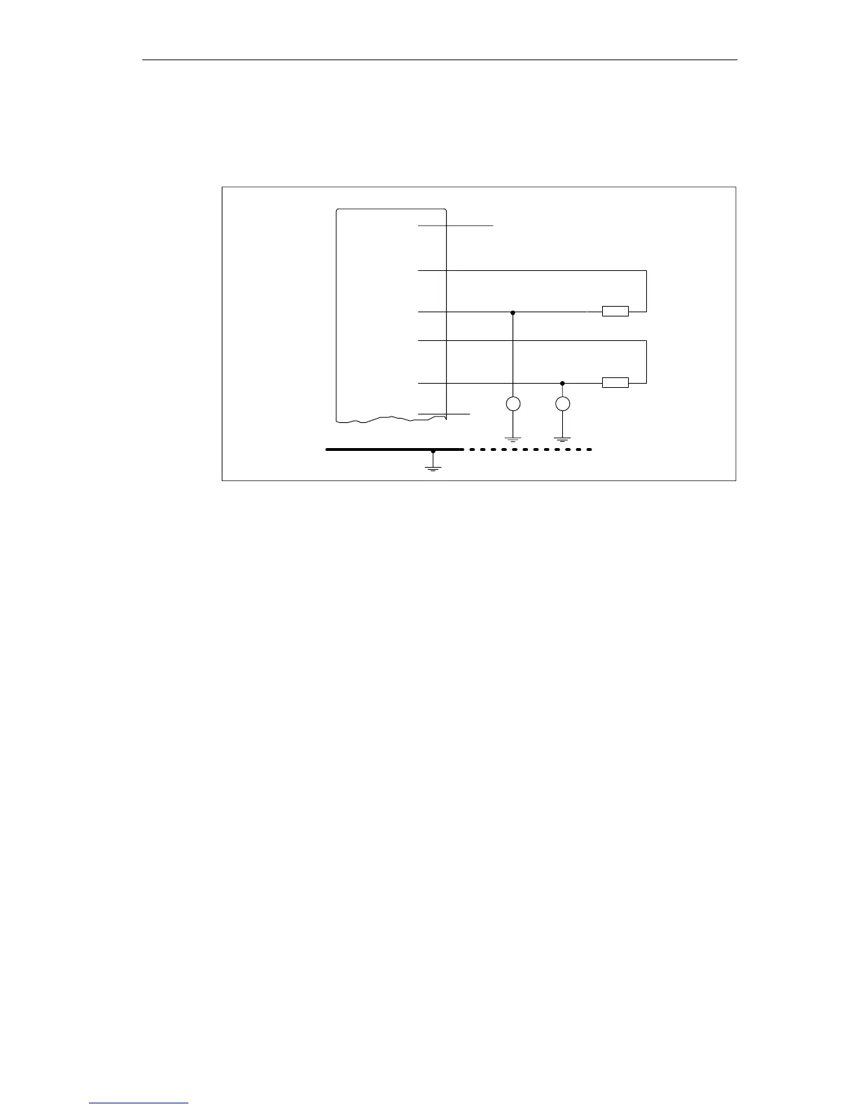
Connecting Loads to the Voltage Output
The following figure shows the wiring of two channels as an example.
+24 V
R
L1
L
+
QV
1
S
1
Ground bus
QV
0
S
0
R
L2
M
0 V
V
CM1
V
CM0
Figure 13-21 Connecting Loads/Actuators via a Three-Wire Connection to a Voltage Output

Table of Contents

Questions and Answers:

Question and Answer IconNeed help?

Do you have a question about the Siemens Simatic M7-400 and is the answer not in the manual?

Siemens Simatic M7-400 Specifications

General IconGeneral
BrandSiemens
ModelSimatic M7-400
CategoryComputer Hardware
LanguageEnglish

Related product manuals