Hardware description
2.2 Interface description
SIMOTION ADI4 - Analog Drive Interface for 4 Axes
16 Manual, 05/2009, 6FC5 297-0BA01-0BP6
2.2.5 Interface (X3): Analog setpoint interface
Connection
50-pin sub D connector
Pin assignment
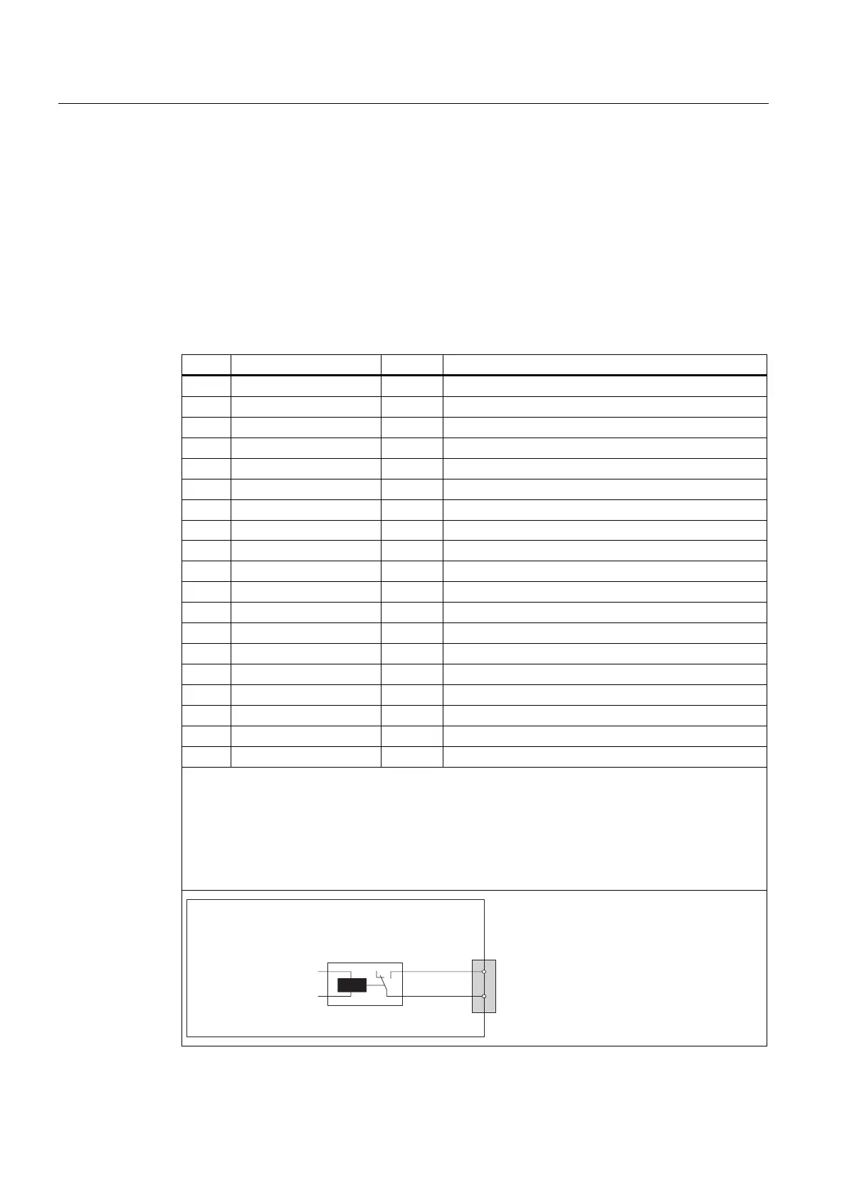
Table 2- 5 Pin assignment: Analog setpoint interface (X3)
Pin Designation Type
1)
Function
1 SW1 VO
3)
Setpoint of Axis 1 (±10 V)
2 BS2 VO Reference for setpoint of Axis 2
3 SW3 VO
3)
Setpoint of Axis 3 (±10 V)
4 BS4 VO Reference for setpoint of Axis 4
5-13 - - -
14 RF1_1 K
2)
"Drive enable" of Axis 1, Relay Contact 1
15 RF2_1 K
2)
"Drive enable" of Axis 2, Relay Contact 1
16 RF3_1 K
2)
"Drive enable" of Axis 3, Relay Contact 1
17 RF4_1 K
2)
"Drive enable" of Axis 4, Relay Contact 1
18-33 - - -
34 BS1 VO Reference for setpoint of Axis 1
35 SW2 VO
3)
Setpoint of Axis 2 (±10 V)
36 BS3 VO Reference for setpoint of Axis 3
37 SW4 VO
3)
Setpoint of Axis 4 (±10 V)
38-46 - - -
47 RF1_2 K
2)
"Drive enable" of Axis 1, Relay Contact 2
48 RF2_2 K
2)
"Drive enable" of Axis 2, Relay Contact 2
49 RF3_2 K
2)
"Drive enable" of Axis 3, Relay Contact 2
50 RF4_2 K
2)
"Drive enable" of Axis 4, Relay Contact 2
1) VO Voltage output
K Relay contact
2) Max. current carrying capacity: 2 A for 150 VDC or 125 VAC
Max. number of switching cycles:
- 24 VDC, 1 A: 10
7
- 24 VDC, 2 A: 10
5
3) Max. current carrying capacity: 10 mA (RL: 1 kW - 2 kW)
$',
;
3LQQXPEHU
5HOD\
6LJQDO
$[LVWR
'ULYHHQDEOH