Hardware description
2.2 Interface description
SIMOTION ADI4 - Analog Drive Interface for 4 Axes
Manual, 05/2009, 6FC5 297-0BA01-0BP6
21
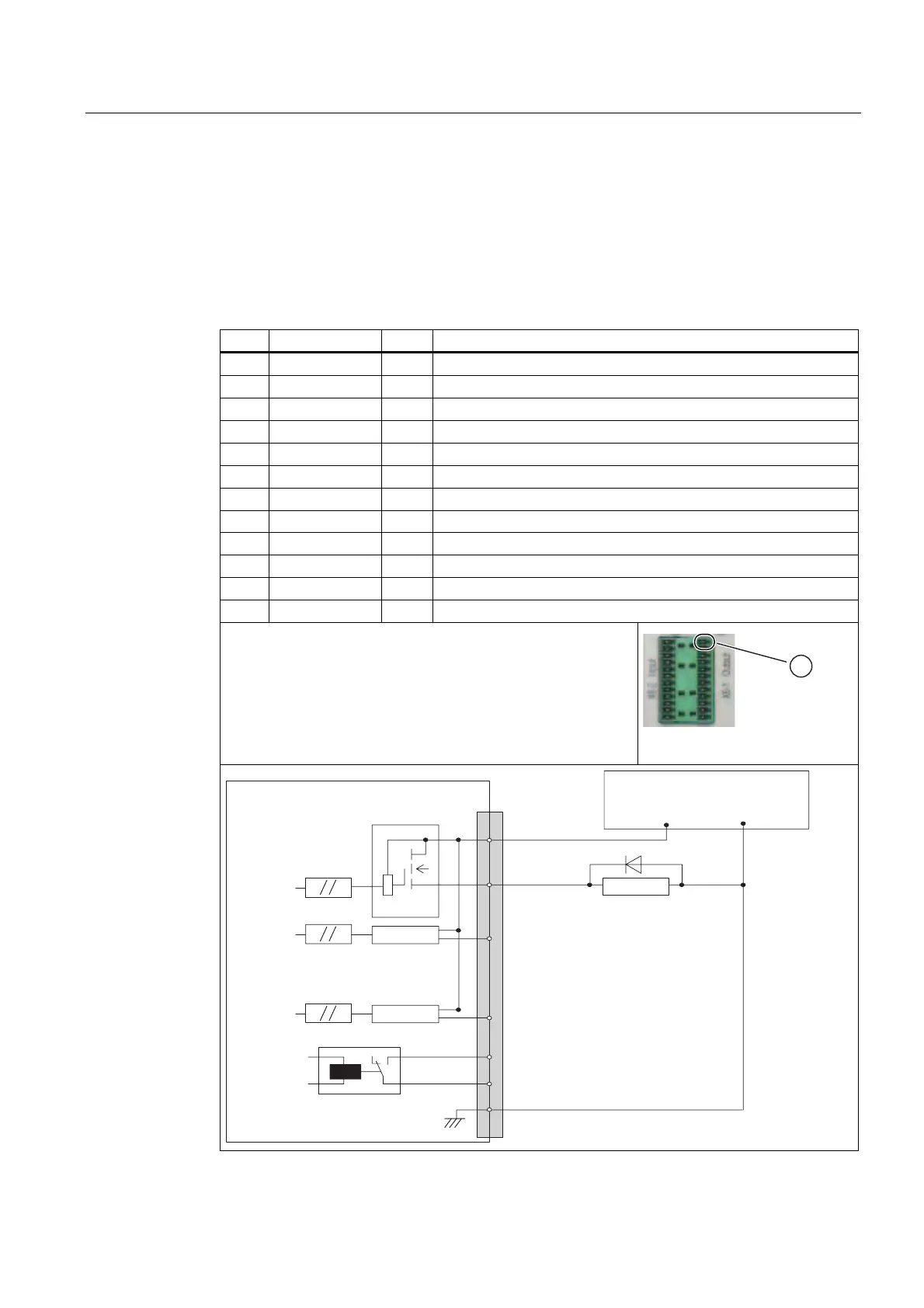
2.2.7 Interface (X6-1): Digital outputs
Connection
Two 12-pin connectors FK-MCP 1.5/15-ST-3.81 by Phoenix
Pin assignment
Table 2- 10 Pin assignment: digital output interface (X6-1)
Pin Designation Type
1)
Function
1 P24EXT2 VI External 24 VDC supply voltage
2 Q0 DO Digital output signal 1
3 Q1 DO Digital output signal 2
4 Q2 DO Digital output signal 3
5 Q3 DO Digital output signal 4
6 DIR1 DO Digital output signal 5 or directional signal of Axis 1
3)
7 DIR2 DO Digital output signal 6 or directional signal of Axis 2
3)
8 DIR3 DO Digital output signal 7 or directional signal of Axis 3
3)
9 DIR4 DO Digital output signal 8 or directional signal of Axis 4
3)
10 RDY1 K
2)
"Ready" signal of Relay Contact 1
11 RDY2 K
2)
"Ready" signal of Relay Contact 2
12 MEXT2 VI Reference of the external supply voltage
1)
VI: Voltage input
DO: Digital output (24 V)
K: Relay contact
2)
Max. current carrying capacity: 2 A for 150 VDC or 125 VAC;
Max. number of switching cycles:
- 24 VDC, 1 A: 10
7
- 24 VDC, 2 A: 10
5
3)
For "unipolar spindle" function (or unipolar motor)
① PIN 1
$',
;ದ
3(;7
0
0(;7
9
9
ಯ5HDG\ರ
3LQQXPEHU
([WSRZHUVXSSO\
9VWDELOL]HG
5HOD\
6LJQDO
2SWRFRXSOHU
'ULYHU
'ULYHU
'ULYHU
5HOD\