Hardware description
2.2 Interface description
SIMOTION ADI4 - Analog Drive Interface for 4 Axes
22 Manual, 05/2009, 6FC5 297-0BA01-0BP6
Supply voltage
To supply the digital outputs with power, an external 24 VDC voltage source must be
connected to X6-1, Pin 1 (P24EXT2).
The reference ground of the external voltage source must be connected to X6-1, Pin 15
(MEXT2).
You will find additional information in Section "
Technical data (Page 31)".
Electrical specification
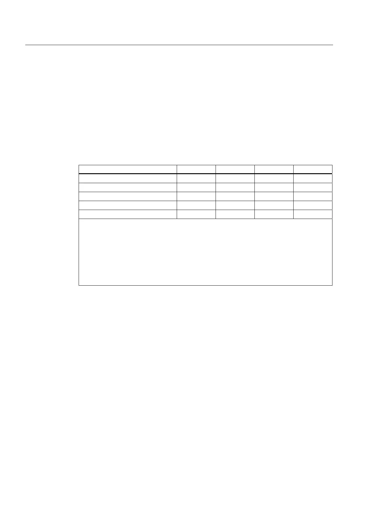
Table 2- 11 Electrical specification of the digital outputs
Digital outputs Min. Typical Max. Nominal
High-level voltage (U
H
) V
CC
- 3 V
1)
V
CC
24 V
Output current I
OUT
- - 500 mA -
Voltage with low level (U
L
) - - - 0 V
Leakage current at low level - 50 µA 400 µA -
Signal delay T
PHL
, T
PLH
2)
- 0.5 ms - -
Supply voltage of the digital outputs
1)
Typical output voltage: V
CC
- I
OUT
*R
ON
- 0.65 V
V
CC
: Current operating voltage P24EXT2
Max. output current I
OUT
: 500 mA
max. short-circuit current: 4 A (max. 100 µs, V
CC
= 24 V)
Internal resistance R
ON
: 0.4 Ω
2)
The PROFIBUS communication time as well as the application cycle time must also be taken into
account.
Incorrect connection (polarity reversal) causes neither high level nor destruction of the outputs.
General electrical properties
● Galvanic isolation using optocouplers
● Current limitation to a maximum 500 mA
● Protection against: short-circuit, overtemperature, and loss of ground
● Automatic disconnection in case of undervoltage