SIMOTION ADI4 - Analog Drive Interface for 4 Axes
Manual, 05/2009, 6FC5 297-0BA01-0BP6
71
Commissioning
4
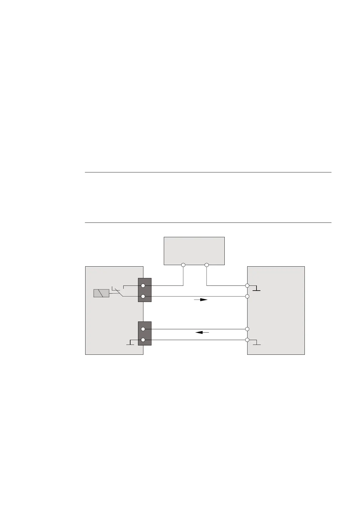
4.1 Wiring of drive ready signals
In order to use the S7 function block FB 401 (MC_POWER) to switch on a drive connected
to the ADI4, the drive must signal its readiness. For this purpose, the ready signal of the
drive must be wired with one of the ready signal inputs "Drive Ready" Axis x (DRVx_RDY),
Interface (X6-2) of the ADI4.
The ready signal must continue to exist at the ADI4 input even after the drive is switched on.
If the signal is cleared, the drive will stop.
Note
Drives without ready signal
If a ready signal is not available for a drive, the corresponding digital ready signal input
"Drive Ready" Axis x (DRVx_RDY) of the ADI4 can be assigned statically with 24 V. The
disadvantage of this is that the S7 function block FB 401 (MC_POWER) can no longer detect
a drive failure. FB 401 returns the status "TRUE" at its output even after a drive failure.
3RZHUVXSSO\
'ULYHHQDEOH$[LV
'ULYH5HDG\$[LV
2XWSXW
'ULYHUHDG\
,QSXW
5HOHDVH
'ULYH
9
9 9
;
5)B
5)B
;
$',
'59B5'<
0287
Figure 4-1 Drive enable for Axis 1 (principle)