Hardware description
2.2 Interface description
SIMOTION ADI4 - Analog Drive Interface for 4 Axes
24 Manual, 05/2009, 6FC5 297-0BA01-0BP6
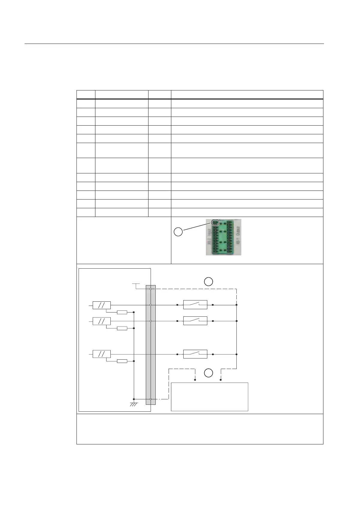
Pin assignment
Table 2- 12 Pin assignment: Digital input interface (X6-2)
Pin Designation Type
1)
Function
1 P24OUT VI 24 VDC supply voltage
2 BERO1 DI Input signal of BERO / external zero mark 1
3 BERO2 DI Input signal of BERO / external zero mark 2
4 BERO3 DI Input signal of BERO / external zero mark 3
5 BERO4 DI Input signal of BERO / external zero mark 4
6 MEPU1 DI Measuring signal of Measuring Input 1 (see "Measuring
inputs" below)
7 MEPU2 DI Measuring signal of Measuring Input 2 (see "Measuring
inputs" below)
8 DRV1_RDY DI "Drive Ready" signal of Axis 1
9 DRV2_RDY DI "Drive Ready" signal of Axis 2
10 DRV3_RDY DI "Drive Ready" signal of Axis 3
11 DRV4_RDY DI "Drive Ready" signal of Axis 4
12 MOUT VI Reference of the supply voltage
1)
VI: Voltage input
DI: Digital input (24 V)
① PIN 1
$',
;ದ
3287
'&9
0
99
3LQQXPEHU
([WSRZHUVXSSO\
3287H[W
9VWDELOL]HG
2SWRFRXSOHU
① Connection if the internal supply voltage P24OUT is used;
the connection in accordance with ② is no longer required.
② Connection if an external supply voltage P24OUText is used;
the connection in accordance with ① is no longer required.