Parameter assignment
3.4 PROFIBUS parameters
SIMOTION ADI4 - Analog Drive Interface for 4 Axes
40 Manual, 05/2009, 6FC5 297-0BA01-0BP6
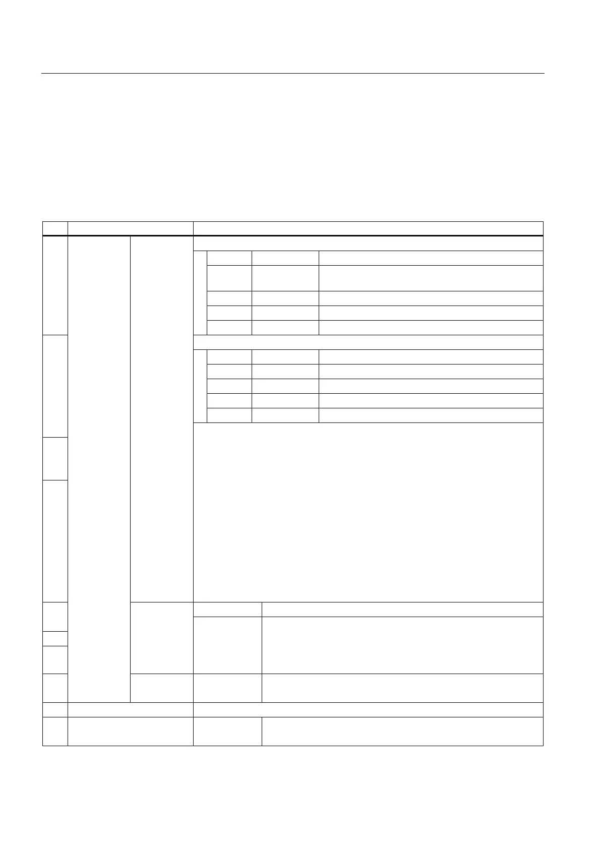
Encoder control word Gx_STW
Description of the encoder control word (extract) for:
● Find reference mark
● On-the-fly measurement
● Encoder error
Table 3- 2 Encoder control word Gx_STW (extract)
Bit Name Signal status, description
Find reference mark: Bit 7 = 0
Bit Meaning Homing using:
0 Function 1: Encoder zero mark (except in "611U conformant
mode")
1 Function 2: Rising edge of external zero mark
2 Function 3: Falling edge of external zero mark
0
3 Function 4: Not used
On-the-fly measurement: Bit 7 = 1
Bit Meaning Measuring using:
0 Function 1: Measuring Input 1 rising edge
1 Function 2: Measuring Input 1 falling edge
2 Function 3: Measuring Input 2 rising edge
3 Function 4: Measuring Input 2 falling edge
1
2
3
Functions
Note
• Bit 0 to 3
Bit x = 1 Function requested
Bit x = 0 Function not requested
• If more than one function is enabled, the values for all functions cannot be read
until all functions have ended and this has been signaled via the relevant status
bit (G1_ZSW, Bit 0 - Bit 3 = 0).
• On-the-fly measurement
The rising and falling edges of the measuring input can be enabled
simultaneously. The measuring input signal is detected according to the direction
of the signal change. The measured values are read out consecutively.
Notice
ADI4 only supports measurement on a rising or falling edge.
• Find reference mark and on-the-fly measurement
Only one of the two functions can be active at a time.
Bit 6, 5, 4 Meaning 4
5
6
Command
000
001
010
011
- -
Activate function x
Read value x
Cancel function x
7
Find
reference
mark
or
On-the-fly
measurement
Mode 0
1
Find reference mark
On-the-fly measurement
: :
15 Encoder error 0
1
No error
Encoder error pending; error code in Gx_XIST2