Technical specifications
12.2 General technical specifications
Drive converter cabinet units
480 Operating Instructions, 07/07, A5E00288214A
Order no.
6SL3710-...
Power [kW] Output current
at 1.25 kHz [A]
Derating factor
at 2.5 kHz
Derating factor
at 5 kHz
Supply voltage 500 – 690 V 3 AC
7LG28-5AA0 75 85 89% 60%
7LG31-0AA0 90 100 88% 60%
7LG31-2AA0 110 120 88% 60%
7LG31-5AA0 132 150 84% 55%
7LG31-8AA0 160 175 87% 60%
7LG32-2AA0 200 215 87% 60%
7LG32-6AA0 250 260 88% 60%
7LG33-3AA0 315 330 82% 55%
7LG34-1AA0 400 410 82% 55%
7LG34-7AA0 450 465 87% 55%
7LG35-8AA0 560 575 85% 50%
7LG37-4AA0 710 735 79% 55%
7Lg38-1AA0 800 810 95% 55%
7LG38-8AA0 900 910 87% 55%
7LG41-0AA0 1000 1025 86% 50%
7LG41-3AA0 1200 1270 79% 40%
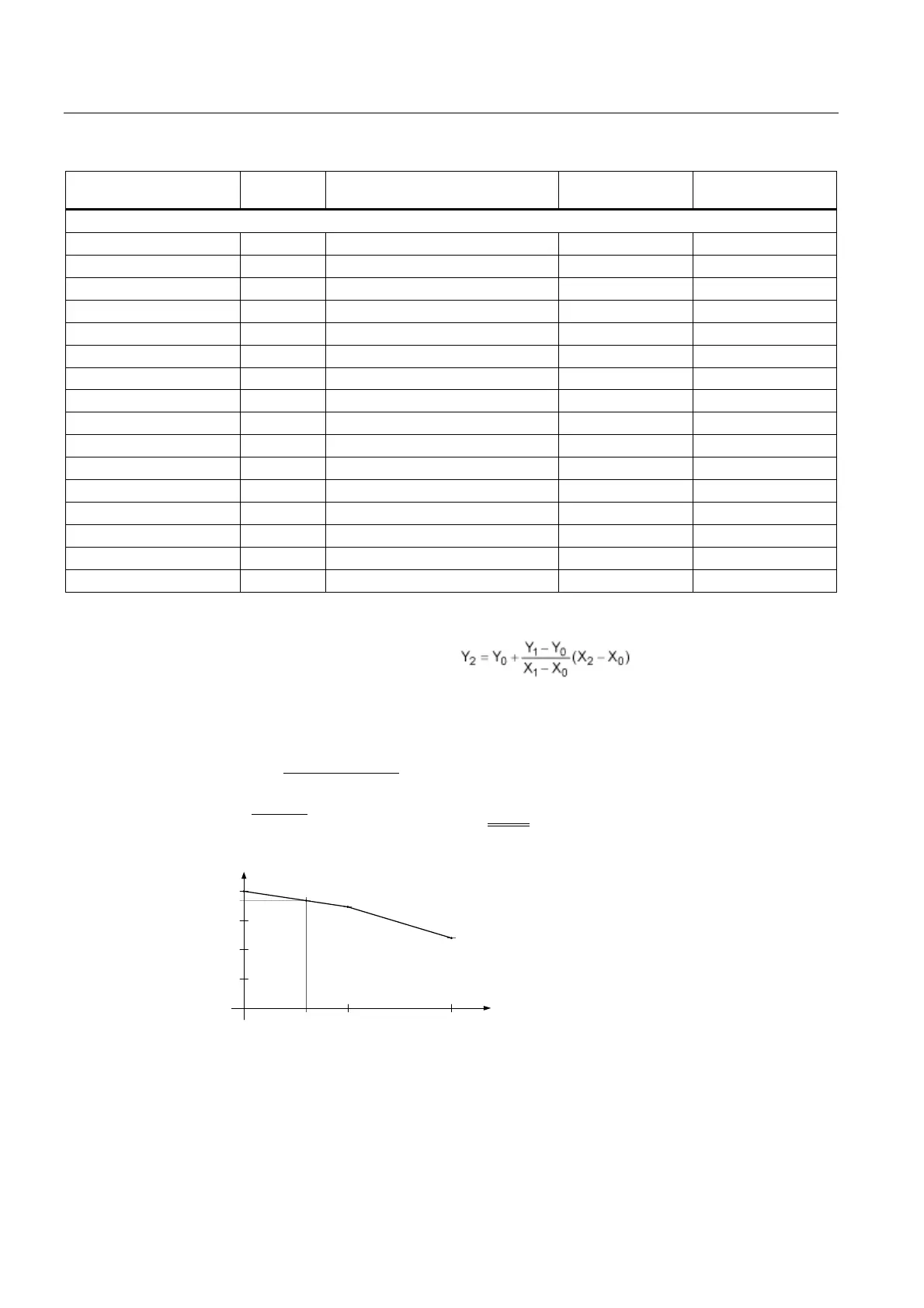
For pulse frequencies in the range between the fixed values, the relevant derating factors
can be determined by means of linear interpolation.
The following formula applies for this:
Example:
The derating factor is required for when X
2
= 2 kHz for 6SL3710-1LE41-0AA0.
X
0
= 1.25 kHz, Y
0
= 100%, X
1
= 2.5 kHz, Y
1
= 87%, X
2
= 2 kHz, Y
2
= ??
N+]
N+]
N+]N+]
N+]N+]
<
'HUDWLQJIDFWRU
3XOVH
N+]
N+] N+]
N+]
f
100 %
50 %
75 %
25 %
60 %
87 %
?? %
Figure 12-1 Calculating derating factors by means of linear interpolation

 Loading...


