Notes
SINUMERIK 802D sl Operating and Service Training Manual Page 2
C11
C11
Section 2
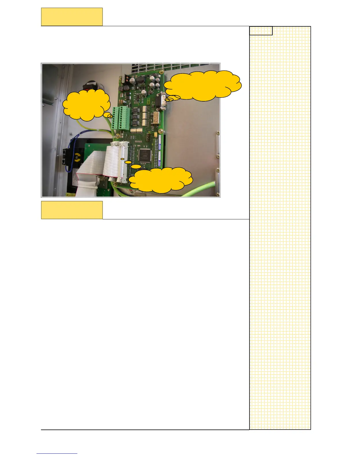
Identification of MCPA in the system
As can bee seen from the picture below, the MCPA board is connected to
the rear of the CNC Co
ntroller itself
, directly to the internal bus.
Analogue Spindle
Interface X
701
MCP Interface
Section 3
Analogue spindle interface test
X1021
X
1020
Description:
X1 – to X1201 on MCP
X2 – to X1202 on MCP
X1021 Pin 1 – to +24V
X1021 Pin 10
– to 0V
X701 Pin 1: Analog
spindle output
(56)
X701 Pin 6: Analog
spindle output 0V reference signal
(14)
X701 Pin 5: Analog d
rive enable RF1(65)
X701 Pin 9: Analog d
rive enable RF2(9)
X701 Pin 4: Digital outp
ut for unipolar spindle –Direction 1
(Refe
rence ground: Pin10 of X1021
)
X701 Pin 3: Digital outp
ut for unipolar spindle – Direction 2
(Refe
rence ground: Pin 10 of X1021
)
Setting the polarity of anal
og spindle output as follows:
• when MD30134 = 0: ±10V : enable X701.5 and X701.9
• when MD30134 = 1: 0-10V: enable X701.4 Direction
X701.3
whe
n MD30134 = 2: 0-10V : Spindle CCW X701.3 Spindle
CW X701.4
No
te:
X1021 Pin 1
necessary for spindle output
Due to the u
se of a 9 pin D sub connector the voltages can only
be tested at the drive en
d of the cable.
To gene
rate a setpoint voltage e.g.S500 M3 should be pro-
gramm
ed in MDI mode.
2.1 Identification of MCPA in the system
3.1 Analogue spindle int
e
rface test