cles in STOCK REMOVAL mode
5
© Siemens AG, 2002. All rights reserved
5-108 SINUMERIK 840D/810D Operator's Guide ManualTurn (BAM) – 08.02 Edition
If the groove is wider than the active tool, then the width is cut in
several steps.
α
αα
α0
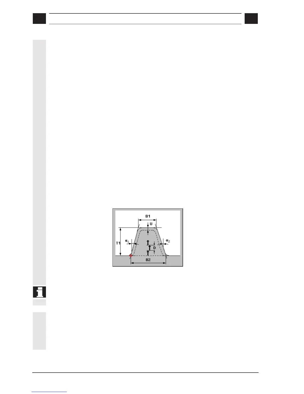
Angle of slope
The oblique angle in relation to the reference axis on which the groove
is to be machined is programmed with parameter
α
αα
α0. The angle can
be set to values of between –180° and +180°.
• Longitudinal groove: α
0
= 0° Þ parallel to Z axis
• Face groove: α
0
= 0° Þ parallel to X axis
• α
0
is positive when rotational direction of X axis Þ Z axis
α
αα
α1
,
α
αα
α2
Edge angle
Flank angles are separately entered so that asymmetrical grooves can
be described. The angles can be set to values of between 0 and
< 90°.
R
n
, FS
n
The groove form is modified through the input of radii/chamfers on the
edge or base (n = 1 ... 4).
D
Infeed depth 1st cut
D=0 : 1st cut is executed straight to the final depth T1.
D>0 : The 1st and 2nd cut are executed at the infeed depth
D on alternate sides, to ensure a better chip clearance
and prevent tool breakage.
All other cuts are executed straight to the final depth
T1.
The lateral infeed for the alternate-sided cutting is automatically
defined in the cycle.
Alternate-sided cutting is not possible when the tool can only reach the
groove base at one position.
U
Finishing allowance
You can specify a finishing dimension for the groove base and flanks.
The workpiece material is rough-cut down to this finishing allowance
during roughing. Finally, a cut is made along the final contour with the
same tool.

 Loading...


