7
Transformations 08.97
7.3 C
linder surface transformation: TRACYL
7
840D
NCU 571
840D
NCU 572
NCU 573
FM-NC
810D
840Di
Siemens AG 2000. All rights reserved
7-242
SINUMERIK 840D/840Di/810D/FM-NC Programming Guide Advanced (PGA)
−
04.00 Edition
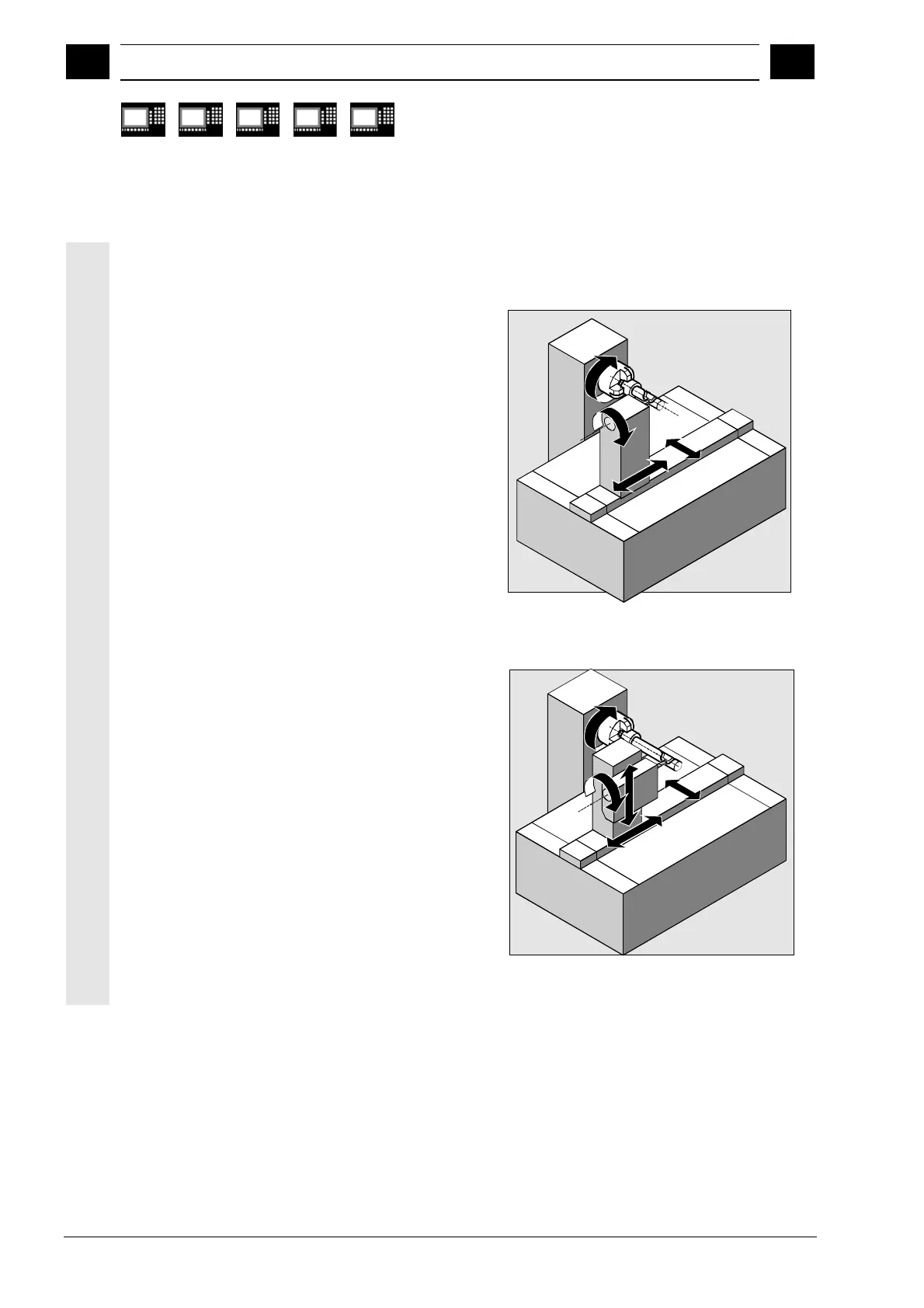
There are two types of cylinder surface coordinate
transformation:
•
without groove side compensation
•
with groove side compensation
Without groove side compensation:
The control transforms the programmed traversing
movements of the cylinder coordinate system into
the traversing movements of the real machine axes:
– Rotary axis
– Infeed axis perpendicular to the rotary axis
– Longitudinal axis parallel to the rotary axis
The linear axes are positioned perpendicular to each
other. The infeed axis intersects the rotary axis.
Z or ZM
ASM
Y or CM
XM
Machine coordinate system
With groove side compensation:
Same kinematics as above, plus:
– Longitudinal axis parallel to the direction of the
circumference
The linear axes are positioned perpendicular to each
other.
The speed control provides defined limits for the
rotary movements.
XM
Z or ZM
ASM
Y or CM
YM
Machine coordinate system

 Loading...


