7
08.97 Transformations
7.3 C
linder surface transformation: TRACYL
7
840D
NCU 571
840D
NCU 572
NCU 573
FM-NC
810D
840Di
Siemens AG 2000. All rights reserved
SINUMERIK 840D/840Di/810D/FM-NC Programming Guide Advanced (PGA)
−
04.00 Edition
7-243
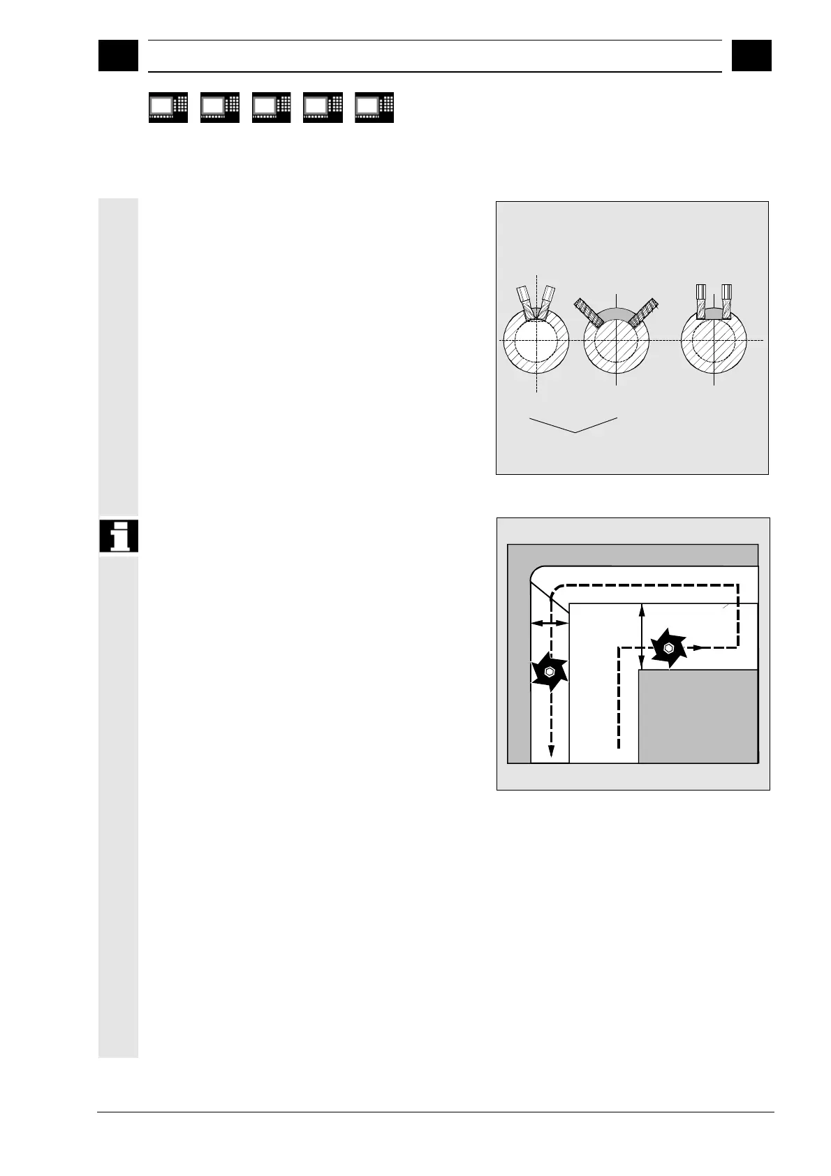
Groove cross section
With axis configuration 1, grooves along the rotary
axis are only limited in parallel if the groove width
matches the tool radius.
Grooves parallel to the circumference (transverse
grooves) are not parallel at the start and end.
Longitudinal
groove
Transverse
groove
Without groove wall
compensation in axis
configuration 2
Longitudinal groove
limited in parallel with
groove wall
compensation in
axis configuration 2
Offset contour normal OFFN
For milling grooves with TRACYL, the groove
•
center line is programmed in the part
•
program, the groove width via OFFN.
OFFN only becomes active when tool radius
compensation
is selected, to protect the side of the groove from
being damaged. Further, OFFN>=tool radius is
advisable to exclude any possible damage to the
opposite side of the groove.
A part program for milling a groove usually consists
of the following steps:
1. Select tool
2. Select TRACYL
3. Select suitable coordinate offset (FRAME)
4. Positioning
5. Programming OFFN
6. Select TRC
7. Approach block (enter TRC and approach side
of the groove)
8. Contour of groove center line
9. Deselect TRC
10. Retract block (exit TRC and retract from side of
groove)
11. Positioning
12. TRAF OOF
13. Select original coordinate offset (FRAME) again
OFFN
Programmed
contour

 Loading...


