cles in STOCK REMOVAL mode
5
© Siemens AG, 2002. All rights reserved
SINUMERIK 840D/810D Operator's Guide ManualTurn (BAM) – 08.02 Edition 5-103
Explanation of parameters
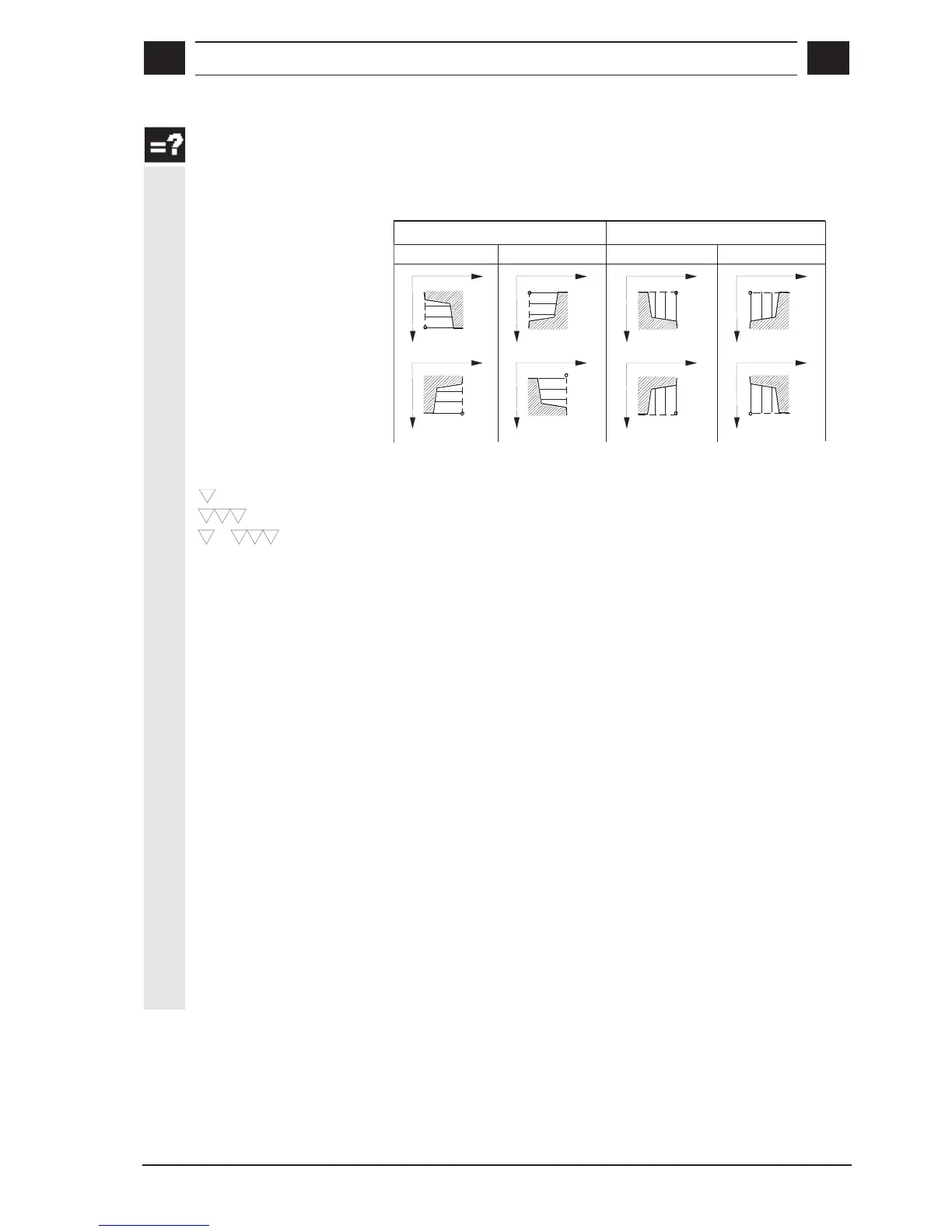
Position parallel Z axis/
X axis
You can define the stock removal position and the stock removal
direction in the coordinate system by means of these settings.
Außen
Innen
Z
X
parallel zur X-Achse (Plan)parallel zur Z-Achse (Längs)
Z
X
Z
X
Z
X
Stirnseite
Z
X
Z
X
Z
X
Z
X
Rückseite
Parallel to X axis (longitudinal)
External Internal
Face end Back plane
Parallel to Z axis (plane)
Machining mode
Select one of the following machining modes:
+
(alternative)
Roughing
Finishing
Complete machining (roughing and finishing)
X0, Z0
Reference points for dimensioning
X1, Z1
Final dimension (only the amount for "inc")
X
m
- Z
m
- α
αα
α1 - α
αα
α2
You can set the specified parameters to other combinations in this
parameter field.
X
m
, Z
m
Intermediate point (only the amount for "inc")
α
αα
α1
Angle of 1st path
α
αα
α2
Angle of 2nd path
R
n
, FS
n
Input of roundings and chamfers (n = 1 ... 3)
D
Infeed depth (enter without sign)
The maximum possible infeed depth for the roughing process is
defined in parameter D. The cycle automatically calculates the infeed
depth to be applied for roughing.

 Loading...


